GE ATP 1000 Installation Instructions - Page 2
Installing the Mounting Plate, Wiring the Touchpad to the Panel, Attaching the Touchpad to
 |
UPC - 782136711486
View all GE ATP 1000 manuals
Add to My Manuals
Save this manual to your list of manuals |
Page 2 highlights
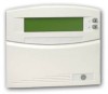
Installing the Mounting Plate 1. Separate the mounting plate from the touchpad by first loosening the screw, then lift the touchpad away from the mounting plate (see Figure 1). Loosen screw, then lift touchpad. Figure 1. Separating the Touchpad from the Mounting Plate 2. For wall mounting, place the mounting plate on the wall and mark the mounting holes (see Figure 2). Be sure to leave a 3-inch clearance below for the touchpad door to open. Mounting Holes Mounting Holes Note Do not overtighten screws or the mounting plate may bind and prevent the touchpad from mounting properly. Figure 2. Mounting Hole Locations 3. Insert anchors into the wall at the marked locations where studs are not present. 4. Align the mounting plate holes with the wall or gang box screw holes and secure the back plate using the screws provided. 5. For wall-mount installations, cut a hole in the wall in the wire access area of the mount- ing plate to pull the wiring cable through. Wiring the Touchpad to the Panel 1. Remove panel AC and backup battery power. 2. Run a 4-conductor, 18- to 22-gauge wire from the panel to the touchpad location (see Table 2). 3. Connect the touchpad +12V, BUS A, BUS B, and GND terminals to the matching panel terminals (see Figure 3 for touchpad terminal identification). GND BUS B BUS A +12V Figure 3. Touchpad Wiring Connections Attaching the Touchpad to the Mounting Plate Align the tabs at the top of the mounting plate with the slots on the touchpad and swing the touchpad bottom toward the mounting plate. Gently tighten the screw into the bottom of the touchpad. 2 ATP1000 Touchpad/Display Installation Instructions
-
 1
1 -
 2
2 -
 3
3 -
 4
4 -
 5
5 -
 6
6
 |
 |
