GE GTUP270EMWW Installation Instructions - Page 10
Plumbing Information, Water Supply Requirements, Drain Requirements, Connecting To Plumbing, - vent location
 |
UPC - 084691229018
View all GE GTUP270EMWW manuals
Add to My Manuals
Save this manual to your list of manuals |
Page 10 highlights
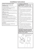
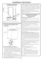
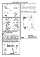
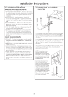
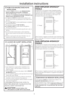
Installation Instructions 10 PLUMBING INFORMATION WATER SUPPLY REQUIREMENTS • HOT AND COLD WATER FAUCETS - Must be within 42" of the appliance water inlet hose connections. The faucets must be 3/4" garden hose-type so inlet hoses can be connected. •WATER PRESSURE - Must be between 10 and 120 pounds per square inch with a maximum unbalance pressure, hot vs. cold flowing, of 10 pounds per square inch. •WATER TEMPERATURE - Water heater should be set to deliver 140° to 150°F (60° to 66°C) in the washer when HOT wash is selected. • SHUT-OFF VALVES - Both hot and cold water shut-off valves (faucets) should be supplied. • LOCATION - Do not install appliance in an area where the temperature will fall below freezing. If appliance is stored or transported in freezing temperatures, be sure all water from the fill and drain systems has been removed. DRAIN REQUIREMENTS • DRAIN RATE - The drain or standpipe must be capable of accepting a discharge at the rate of 16 gallons per minute. • DRAIN HEIGHT - The drain height must be 33" minimum and 96" maximum. • STANDPIPE DIAMETER - The standpipe diameter must be 1-1/2" minimum. There MUST be an air gap around the drain hose in the standpipe. A snug fit can cause a siphoning action. • SIPHON BREAK KIT - For a drain facility less than 33" high, the hose, coupling and clamps provided in the machine must be used and, in addition, a siphon break MUST be installed on the back of the machine. Use Siphon Break Kit WH49X228 and follow instructions in the kit. 11 CONNECTING TO PLUMBING FACILITIES c H If not installed, install rubber washer in one end of hot water hose. Thread hot water hose onto connection labeled H at top rear of washer. Hand tighten, plus an additional 1/8 turn with pliers. If not installed, install rubber washer in one end of cold water hose. Thread cold water hose onto connection labeled C at top rear of washer. Hand tighten, plus an additional 1/8 turn with pliers. Move appliance as close to final location as possible, leaving room for you to make water, drain, electrical and vent connections to your home. NOTE: If longer drain hose is required, order drain hose extension kit, GE part number WH49X301. Connect additional drain hose (contained in kit) to original hose with hose clamp (contained in kit). Insert free end of drain hose into drain opening of your home up to drain hose stopper (do not remove hose stopper it prevents siphoning). If water valves and drain are built into wall, fasten drain hose to one of water hoses with cable tie provided (ribbed side on inside). If your drains is a standpipe, fasten drain hose to standpipe with cable tie provided. 10
-
 1
1 -
2
-
3
-
4
-
 5
5 -
 6
6 -
 7
7 -
 8
8 -
 9
9 -
 10
10 -
 11
11 -
 12
12 -
 13
13 -
 14
14 -
 15
15 -
16
-
17
-
18
-
19
-
20
-
21
-
22
-
23
-
24
 |
 |
