GE GTUP270EMWW Installation Instructions - Page 5
Reconnecting Gas - 27
 |
UPC - 084691229018
View all GE GTUP270EMWW manuals
Add to My Manuals
Save this manual to your list of manuals |
Page 5 highlights
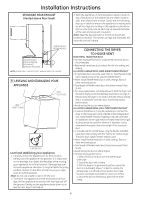
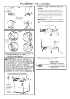
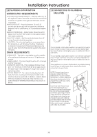
Installation Instructions GAS SUPPLY • A 1/8-in.National Pipe Taper thread plugged tapping, accessible for test gauge connection, must be installed immediately upstream of the gas supply connection to the dryer. Contact your local gas utility should you have questions on the installation of the plugged tapping. • Supply line is to be 1/2-in. rigid pipe and equipped with an accessible shut-off within 6 ft. of, and in the same room with the dryer. •Use pipe thread sealer compound or Teflon tape appropriate for natural or LP gas. • You must use with this dryer a flexible metal connector listed connector ANSI Z21.24 / CSA 6.10. The length of the connect shall not exceed 3 ft. • Connect flexible metal connector to dryer and gas supply. • Open shut-off valve. 27" APPLY PIPE COMPOUND TO THE ADAPTOR AND APPLIANCE GAS INLET. 27" 3 RECONNECTING GAS Listed connector ANSI Z21.24 / CSA 6.10 24" NEW METAL FLEXIBLE GAS LINE CONNECTOR INLET FROM APPLIANCE BACK OF APPLIANCE 24" & 27" FLARE NPT ADAPTOR 27" ONLY 3/8" NPT INLET FROM APPLIANCE 27" ONLY 45° ELBOW 27" ONLY NEW METAL FLEXIBLE GAS LINE CONNECTOR ADAPTOR 1/8" NPT PIPE PLUG FOR CHECKING GAS INLET PRESSURE SHUT-OFF VALVE PIPE SIZE AT LEAST 1/2" ITEMS NOT SUPPLIED FLOOR Note: The connector and fittings are designed for use only on the original installation and are not to be reused for another appliance or at another location. Keep flare end of adaptor free of grease, oil and thread sealant. Caution: Use adapters as shown. Connector nuts must not be connected directly to pipe threads. 5 TIGHTEN THE FLEXIBLE GAS LINE TO THE ADAPTOR USING 2 ADJUSTABLE WRENCHES. 24" APPLY PIPE COMPOUND TO APPLIANCE INLET 24" TIGHTEN THE FLEXIBLE GAS LINE TO THE APPLIANCE INLET USING 2 ADJUSTABLE WRENCHES. 24" & 27" APPLY PIPE COMPOUND TO ALL MALE THREADS 24" & 27" TIGHTEN ALL CONNECTIONS USING TWO ADJUSTABLE WRENCHES. DO NOT OVERTORQUE GAS CONNECTIONS!
-
 1
1 -
 2
2 -
 3
3 -
 4
4 -
 5
5 -
 6
6 -
 7
7 -
 8
8 -
 9
9 -
 10
10 -
 11
11 -
12
-
13
-
14
-
15
-
16
-
17
-
18
-
19
-
20
-
21
-
22
-
23
-
24
 |
 |
