GE GTUP270EMWW Installation Instructions - Page 2
Installation Instructions - manual
 |
UPC - 084691229018
View all GE GTUP270EMWW manuals
Add to My Manuals
Save this manual to your list of manuals |
Page 2 highlights
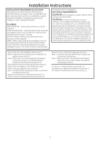
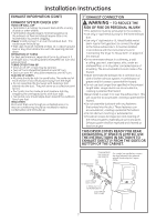
Installation Instructions INSTALLATION REQUIREMENTS LOCATION This appliance must be installed on firm flooring to minimize vibration during spin cycle. Concrete flooring is best, but wood base is sufficient, provided floor support meets FHA standards. This appliance should not be installed on rugs or exposed to weather. PLUMBING WATER PRESSURE - Must be 20 psi minimum to 120 psi maximum. WATER TEMPERATURE - Household water heater should be set to deliver water at 120° to 150°F (50° to 66°C) IN THE WASHER when hot wash is selected. SHUTOFF VALVES - Both hot and cold shutoff valves (faucets) should be supplied. DRAIN - Water may be drained into standpipe or set tub. Discharge height MUST NOT BE LESS THAN 30 INCHES, and no more than 6 feet above the base of the washer. Standpipe must be 1-1/2 inches minimum inside diameter and must be open to atmosphere. ELECTRICAL REQUIREMENTS CAUTION: Before plugging in washer, read the follow- ing electrical requirements. CAUTION: For personal safety, do not use an extension cord or adapter plug with this appliance. Do not, under any circumstances, cut or remove the third grounding prong from the power cord. Follow national electrical codes and ordinances. This appliance must be supplied with the voltage and frequency indicated on the rating plate (located at the top of the dryer front panel), and connected to an individual, properly grounded branch circuit, protected by a 15- or 20-amp circuit breaker or time-delay fuse. If the electric supply provided does not meet the above requirements, call a licensed electrician. Step 1 Verify Your Gas Installation (see section 2). Step 2 Prepare the Area and Exhaust for Installation of appliance (see section 1). Step 3 Check and Insure the Existing External Exhaust is Clean (see section 1) and Meets Attached Installation Specifications (see section 6). Step 4 Remove the Foam Shipping Pads (see section 1). Step 5 Move the appliance to the Desired Location. Step 6 Level your appliance (see section 8). Step 7 Connect the Gas Supply (see section 3) and check for leaks (see section 4). Step 8 Connect the External Exhaust (see section 7). Step 9 Connect to plumbing facilities (see section 11). Step 10 Connect the Power Supply (see section 5). Step 11 Check the Operation of the Power Supply, Gas Connections, and Venting. Step 12 Place the Owners Manual and the Installation Instructions in a Location Where They Will Be Noticed By the Owner. For Alcove or Closet Installation see section 13. For Bathroom or Bedroom Installation see section 14. For Mobile or Manufactured Home see section 12. 2
-
 1
1 -
 2
2 -
 3
3 -
 4
4 -
 5
5 -
 6
6 -
 7
7 -
 8
8 -
9
-
10
-
11
-
12
-
13
-
14
-
15
-
16
-
17
-
18
-
19
-
20
-
21
-
22
-
23
-
24
 |
 |
