GE GTUP270EMWW Installation Instructions - Page 6
Leak Test, Electrical Connection, Information, Electrical Requirements, To Reduce The, Risk Of Fire
 |
UPC - 084691229018
View all GE GTUP270EMWW manuals
Add to My Manuals
Save this manual to your list of manuals |
Page 6 highlights
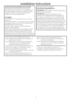
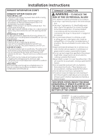
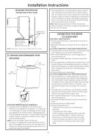
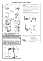
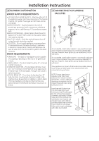
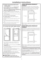
Installation Instructions 4 LEAK TEST WARNING: NEVER USE AN OPEN FLAME TO TEST FOR GAS LEAKS. ENSURE PROPER GROUND EXISTS BEFORE USE. 5 ELECTRICAL CONNECTION INFORMATION WARNING - TO REDUCE THE RISK OF FIRE, ELECTRICAL SHOCK, AND PERSONAL INJURY: • DO NOT USE AN EXTENSION CORD OR AN ADAPTER PLUG WITH THIS APPLIANCE. Dryer must be electrically grounded in accordance with local codes and ordinances, or in the absence of local codes, in accordance with the NATIONAL ELECTRICAL CODE, ANSI/NFPA NO. 70. ELECTRICAL REQUIREMENTS This appliance must be supplied with 120V, 60Hz, and connected to a properly grounded branch circuit, protected by a 15- or 20- amp circuit breaker or timedelay fuse. If electrical supply provided does not meet the above specifications, it is recommended that a licensed electrician install an approved outlet. WARNING - THIS DRYER IS EQUIPPED A THREE-PRONG (GROUNDING) PLUG FOR YOUR PROTECTION AGAINST SHOCK HAZARD AND SHOULD BE PLUGGED DIRECTLY INTO A PROPERLY GROUNDED THREE-PRONG RECEPTACLE. DO NOT CUT OR REMOVE THE GROUNDING PRONG FROM THIS PLUG. 6 EXHAUST INFORMATION WARNING - IN CANADA AND IN THE UNITED STATES, THE REQUIRED EXHAUST DUCT DIAMETER IS 4 IN (102mm). DO NOT USE DUCT LONGER THAN SPECIFIED IN THE EXHAUST LENGTH TABLE. Using exhaust longer than specified length will: • Increase the drying times and the energy cost. • Reduce the dryer life. • Accumulate lint, creating a potential fire hazard. The correct exhaust installation is YOUR RESPONSIBILITY. Problems due to incorrect installation are not covered by the warranty. Remove and discard existing plastic or metal foil transition duct and replace with UL listed transition duct. The MAXIMUM ALLOWABLE duct length and number of bends of the exhaust system depends upon the type of duct, number of turns, the type of exhaust hood (wall cap), and all conditions noted below. The maximum duct length for rigid metal duct is shown in the table below. 27" DRYER EXHAUST LENGTH RECOMMENDED MAXIMUM LENGTH Exhaust Hood Types Recommended Use only for short run installations 4" DIA. 4" DIA. 4" DIA. No. of 90º Elbows 0 1 2 3 4" Rigid Metal 56 Feet 46 Feet 34 Feet 32 Feet 2-1/2" Rigid Metal 42 Feet 36 Feet 28 Feet 18 Feet 24" DRYER EXHAUST LENGTH RECOMMENDED MAXIMUM LENGTH Exhaust Hood Types Recommended Use only for short run installations 4" DIA. 4" DIA. 4" DIA. No. of 90º Elbows 0 1 2 4" Rigid Metal 43 Feet 33 Feet 24 Feet 2-1/2" Rigid Metal 36 Feet 26 Feet 16 Feet 6
-
 1
1 -
 2
2 -
 3
3 -
 4
4 -
 5
5 -
 6
6 -
 7
7 -
 8
8 -
 9
9 -
 10
10 -
 11
11 -
 12
12 -
13
-
14
-
15
-
16
-
17
-
18
-
19
-
20
-
21
-
22
-
23
-
24
 |
 |
