GE GTUP270EMWW Installation Instructions - Page 4
Warning, Warning - installation instructions
 |
UPC - 084691229018
View all GE GTUP270EMWW manuals
Add to My Manuals
Save this manual to your list of manuals |
Page 4 highlights
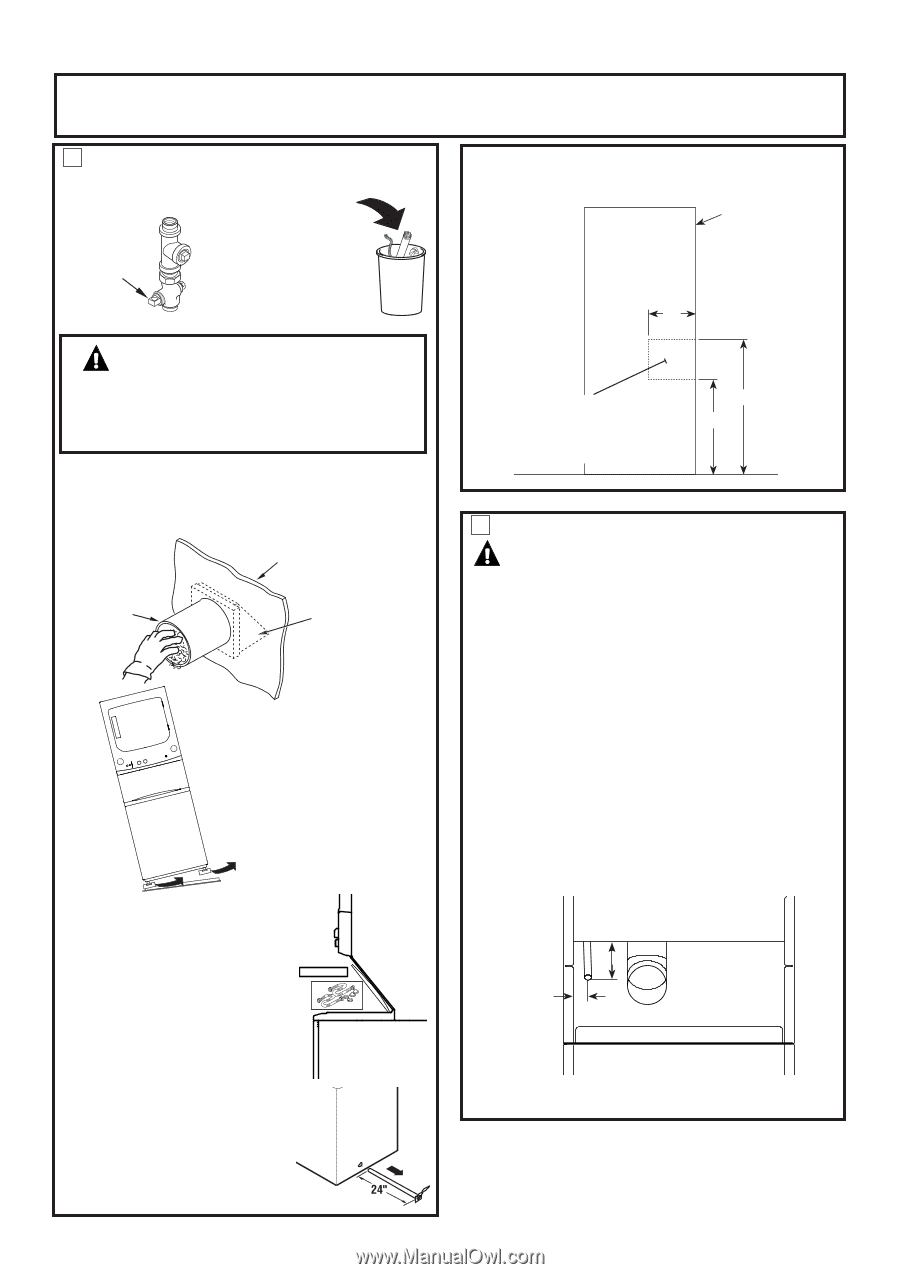
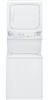
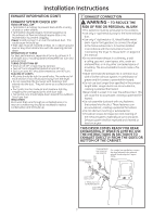
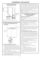
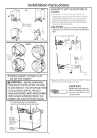
Installation Instructions Minimum Clearance Other Than Alcove or Closet Installation Minimum clearance to combustible surfaces and for air opening are: 0 in. clearance both sides and 1 in. rear. Consideration must be given to provide adequate clearance for installation and service. 1 PREPARING FOR INSTALLATION OF NEW APPLIANCE DISCONNECTING GAS TURN GAS SHUT-OFF VALVE TO THE OFF POSITION. DISCONNECT AND DISCARD OLD FLEXIBLE GAS CONNECTOR AND OLD TRANSITION DUCTING MATERIAL. REPLACE WITH NEW CSA(AGA) APPROVED FLEXIBLE GAS LINE CONNECTOR AND UL APPROVED TRANSITION DUCT. WARNING - NEVER REUSE OLD FLEXIBLE CONNECTORS. The use of old flexible connectors can cause leaks and personal injury. Always use new flexible connectors when installing gas appliances. REMOVING LINT FROM WALL EXHAUST OPENING • Remove and discard existing plastic or metal foil transition duct and replace with UL listed transition duct . WALL INTERNAL DUCT OPENING CHECK THAT EXHAUST HOOD DAMPER OPENS AND CLOSES FREELY. TILT THE APPLIANCE SIDEWAYS AND REMOVE THE FOAM SHIPPING PADS BY PULLING AT THE SIDES AND BREAKING THEM AWAY FROM THE APPLIANCE LEGS. BE SURE TO REMOVE ALL OF THE FOAM PIECES AROUND THE LEGS. After the machine is in the home, remove remaining packing material/ carton from washer. DO NOT REMOVE SHIPPING ROD AT THIS TIME. Remove styrofoam block. Remove the bag containing the Washer hoses and parts parts from tub. Put styrofoam block back in tub opening to hold tub in place during the rest of installation. Move washer close to final position. Make sure there is at least a 24" clearance on right side of washer to remove shipping bar. PULL SHIPPING BAR OUT USING YELLOW PLASTIC HANDLE. Keep bar so it can be reinstalled if washer is ever moved again. NEW HOME OR REMODELING FAUCETS/ DRAIN STANDPIPE/ELECTRICAL LOCATION Right side of Unitized Washer/ Dryer. 12" Locate spigots, drain standpipe and electrical plug in this area 42" 33" FLOOR 2 GAS REQUIREMENTS WARNING • Installation must conform to local codes and ordinances, or in their absence, the NATIONAL FUEL GAS CODE, ANSI Z223. • This gas dryer is equipped with a Valve & Burner Assembly for use only with natural gas. Using conversion kit WE25X0217, your local service organization can convert this dryer for use with propane (LP) gas. ALL CONVERSIONS MUST BE MADE BY PROPERLY TRAINED AND QUALIFIED PERSONNEL AND IN ACCORDANCE WITH LOCAL CODES AND ORDINANCE REQUIREMENTS. • The appliance must be disconnected from the gas supply piping system during any pressure testing of that system at a test pressure in excess of 0.5 PSI (3.4 KPa). • The appliance must be isolated from the gas supply piping system by closing the equipment shut-off valve during any pressure testing of the gas supply piping of test pressure equal to or less than 0.5 PSI (3.4 KPa). 27" GAS SUPPLY CONNECTION 3" 3" Note: 24" Gas supply connection has a flexible hose thus dimensions will vary. 4
-
 1
1 -
 2
2 -
 3
3 -
 4
4 -
 5
5 -
 6
6 -
 7
7 -
 8
8 -
 9
9 -
 10
10 -
11
-
12
-
13
-
14
-
15
-
16
-
17
-
18
-
19
-
20
-
21
-
22
-
23
-
24
 |
 |