GE PGP989SNSS Use and Care Manual - Page 23
Electrical Connections, ELECTRICAL SUPPLY, GAS SUPPLY
 |
UPC - 084691172550
View all GE PGP989SNSS manuals
Add to My Manuals
Save this manual to your list of manuals |
Page 23 highlights
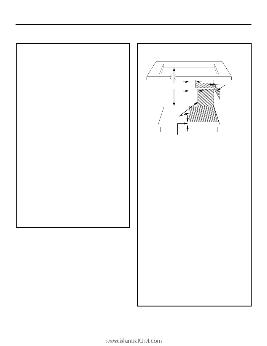
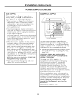
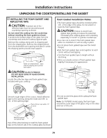
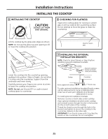
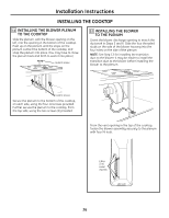
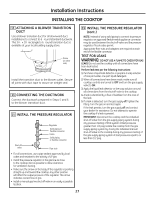
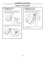
Installation Instructions POWER SUPPLY LOCATIONS GAS SUPPLY: These cooktops are designed to operate on natural gas at 4″ of water column pressure or on LP gas at 10″ of water column pressure. • These cooktops are shipped from the factory set for natural gas. If you decide to use this cooktop with LP gas, conversion adjustments must be made by a service technician or other qualified person. • The pressure regulator must be connected in series with the manifold of the cooktop and must remain in series with the supply line regardless of type of gas being used. For proper operation, the maximum inlet pressure to the regulator must be no more than 10″ water column pressure for natural gas and 14″ water column pressure for LP gas. • When checking the regulator, the inlet pressure must be at least 1″ greater than the regulator output setting. If the regulator is set for 4″ of water column pressure, the inlet pressure must be at least 5″. If the regulator is set for 10″ of water column pressure, the inlet pressure must be at least 11″. For ease of installation, and if local codes permit, the gas supply line into the cooktop should be 1/2″ or 3/4″ ID flexible metal appliance connector, three to five feet long. NOTE: Purchase a new flexible line. DO NOT USE AN OLD PREVIOUSLY USED LINE. • Make gas connection through rear wall, or on cabinet floor at rear, as illustrated. ELECTRICAL SUPPLY: 291⁄2″ 2″ min 3″ min CL Gas pipe location Electrical outlet 12″ above cabinet floor (mount on side or back cabinet wall 2″ min. from centerline) 4″ (to clear toe kick area) The built-in gas downdraft cooktop features pilotless electric ignition for energy savings and reliability. It operates on a 120-volt, 60-Hz power supply. A separate circuit, protected by a 15-amp time-delay fuse or circuit breaker, is required. • A properly grounded 3-prong receptacle should be located within reach of cooktop's four foot power cord. IMPORTANT: (Please read carefully.) FOR PERSONAL SAFETY, THIS APPLIANCE MUST BE PROPERLY GROUNDED. The power cord of this appliance is equipped with a three-prong (grounding) plug which mates with a standard three-prong grounding wall receptacle to minimize the possibility of electric shock hazard from this appliance. The customer should have the wall receptacle and circuit checked by a qualified electrician to make sure the receptacle is properly grounded and has correct polarity. Where a standard two-prong wall receptacle is encountered, it is the personal responsibility and obligation of the customer to have it replaced with a properly grounded three-prong wall receptacle. Do Not, Under Any Circumstances, Cut Or Remove The Third (ground) Prong From The Power Cord. Do not use an extension cord. 23
-
 1
1 -
2
-
3
-
4
-
5
-
6
-
7
-
8
-
9
-
10
-
11
-
12
-
13
-
14
-
15
-
16
-
17
-
 18
18 -
 19
19 -
 20
20 -
 21
21 -
 22
22 -
 23
23 -
 24
24 -
 25
25 -
 26
26 -
 27
27 -
 28
28 -
29
-
30
-
31
-
32
-
33
-
34
-
35
-
36
-
37
-
38
-
39
-
40
-
41
-
42
-
43
-
44
-
45
-
46
-
47
-
48
-
49
-
50
-
51
-
52
-
53
-
54
-
55
-
56
-
57
-
58
-
59
-
60
-
61
-
62
-
63
-
64
-
65
-
66
-
67
-
68
-
69
-
70
-
71
-
72
 |
 |