GE PGP989SNSS Use and Care Manual - Page 27
Installing The Cooktop, Warning, Attaching A Blower Transition, Connecting The Ductwork
 |
UPC - 084691172550
View all GE PGP989SNSS manuals
Add to My Manuals
Save this manual to your list of manuals |
Page 27 highlights
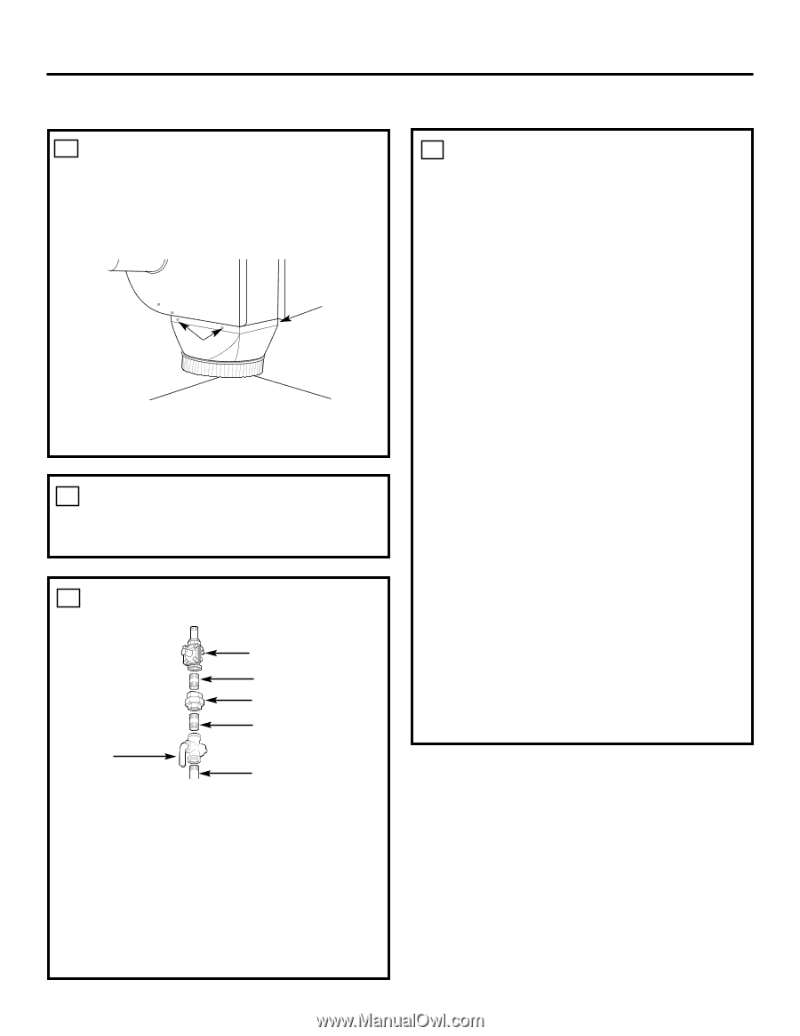
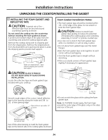
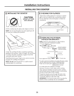
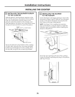
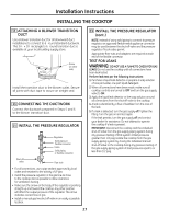
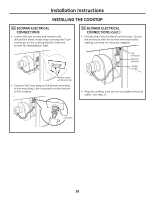
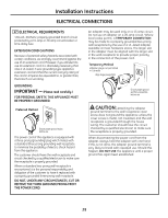
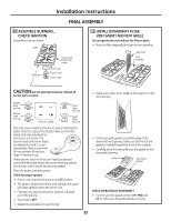
Installation Instructions INSTALLING THE COOKTOP 13 ATTACHING A BLOWER TRANSITION DUCT Use a blower transition duct for all downward duct installations to connect to 6″ round standard ductwork. This 31⁄4″ x 10″ rectangle to 6″ round transition duct is available at your local building supply store. Screws Screw (on other side) Install the transition duct to the blower outlet. Secure all joints with duct tape to assure an airtight seal. 14 CONNECTING THE DUCTWORK Connect the ductwork prepared in Steps 5 and 6 to the blower transition duct. 15 INSTALL THE PRESSURE REGULATOR Regulator Solid piping or flexible connector Union Solid piping or flexible connector Shut-off valve Pipe stub • For all connections, use a pipe sealant approved by local codes and resistant to the activity of LP gas. • Install the pressure regulator in the gas line as close to the cooktop inlet as possible to allow clearance for ventilation ducting. • Make sure the arrow on the body of the regulator is pointing straight up and toward the cooktop. Any other position will affect the output pressure of the regulator. This arrow indicates correct flow of gas. • Install a manual gas line shut-off valve in an easily accessible location. 15 INSTALL THE PRESSURE REGULATOR (cont .) NOTE: Instead of using solid piping to connect to pressure regulator, an approved flexible metal appliance connector may be used between the shut-off valve and the pressure regulator, if local codes permit. Appropriate flare nuts and adapters are required at each end of the flexible connector. TEST FOR LEAKS WARNING: DO NOT USE A FLAME TO CHECK FOR GAS LEAKS! Do not use the cooktop until all connections have been leak tested. Perform leak test per the following instructions: 1. Purchase a liquid leak detector or prepare a soap solution of one part water, one part liquid detergent. 2. When all connections have been made, make sure all cooktop controls are turned to OFF and turn the gas supply valve to ON. 3. Apply the liquid leak detector or the soap solution around all connections from the shut-off valve to the cooktop. 4. A leak is identified by a flow of bubbles from the area of the leak. 5. If a leak is detected, turn the gas supply off. Tighten the fitting. Turn the gas on and test again. If the leak persists, turn the gas supply off and contact your dealer for assistance. Do not attempt to operate the cooktop if a leak is present. IMPORTANT: Disconnect the cooktop and the individual shut-off valve from the gas supply piping system during any pressure testing of that system at test pressures greater than 1/2 psig. Isolate the cooktop from the gas supply piping system by closing the individual manual shut-off valve to the cooktop during any pressure testing of the gas supply piping system at test pressures equal to or less than 1/2 psig. 27
-
 1
1 -
2
-
3
-
4
-
5
-
6
-
7
-
8
-
9
-
10
-
11
-
12
-
13
-
14
-
15
-
16
-
17
-
18
-
19
-
20
-
21
-
 22
22 -
 23
23 -
 24
24 -
 25
25 -
 26
26 -
 27
27 -
 28
28 -
 29
29 -
 30
30 -
 31
31 -
 32
32 -
33
-
34
-
35
-
36
-
37
-
38
-
39
-
40
-
41
-
42
-
43
-
44
-
45
-
46
-
47
-
48
-
49
-
50
-
51
-
52
-
53
-
54
-
55
-
56
-
57
-
58
-
59
-
60
-
61
-
62
-
63
-
64
-
65
-
66
-
67
-
68
-
69
-
70
-
71
-
72
 |
 |