GE PGP989SNSS Use and Care Manual - Page 25
Installing The Cooktop, Caution, Checking For Flatness, Installing The Optional, Installation Brackets
 |
UPC - 084691172550
View all GE PGP989SNSS manuals
Add to My Manuals
Save this manual to your list of manuals |
Page 25 highlights
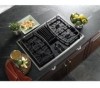
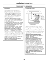
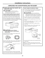
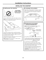
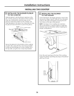
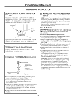
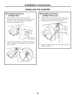
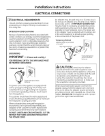
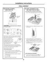
Installation Instructions INSTALLING THE COOKTOP 8 INSTALLING THE COOKTOP CAUTION: DO NOT LIFT FROM VENT OPENING. 9 CHECKING FOR FLATNESS Inspect the cooktop glass for rocking or uneven gap on all four sides at the countertop surface. Do not attempt to force the glass to meet the countertop. Lift the cooktop by the glass side edges as shown. NOTE: Do not use the glass top vent opening to lift or move the cooktop into position. Check for uneven gaps Lower the cooktop into the countertop opening, guiding it into position. Glass is fragile-do not allow it to drop onto the countertop. Support from the underside and lower slowly. Carefully remove your fingers one corner at a time to lower the cooktop into position. NOTE: Do not use Silicone RTV or caulk to bond cooktop glass to countertop. 10 INSTALLING THE OPTIONAL INSTALLATION BRACKETS NOTE: Check for glass flatness in Step 9 before installing optional installation brackets. Optional installation bracket and thumb screw (not included) Cooktop Countertop Screws supplied with cooktop Thumb screw To order optional installation brackets/thumb screws, call the National Parts Center at 800.626.2002. Order two of each part: WB02X11331 Bracket WB01X10353 Screw To install optional installation brackets: Remove 2 screws on both sides under cooktop. Align optional installation bracket under cooktop and reinstall screws through the slot in the bracket. Do this on both sides of the cooktop. Thread the thumb screw through the hole in the bracket and tighten to secure the cooktop to the countertop. Repeat on the other side. IMPORTANT: Turn thumb screw until it touches the bottom of the countertop. Do not overtighten. 25
-
 1
1 -
2
-
3
-
4
-
5
-
6
-
7
-
8
-
9
-
10
-
11
-
12
-
13
-
14
-
15
-
16
-
17
-
18
-
19
-
 20
20 -
 21
21 -
 22
22 -
 23
23 -
 24
24 -
 25
25 -
 26
26 -
 27
27 -
 28
28 -
 29
29 -
 30
30 -
31
-
32
-
33
-
34
-
35
-
36
-
37
-
38
-
39
-
40
-
41
-
42
-
43
-
44
-
45
-
46
-
47
-
48
-
49
-
50
-
51
-
52
-
53
-
54
-
55
-
56
-
57
-
58
-
59
-
60
-
61
-
62
-
63
-
64
-
65
-
66
-
67
-
68
-
69
-
70
-
71
-
72
 |
 |
