Gigabyte G1.Sniper M5 User Manual - Page 29
F_AUDIO Front Panel Audio Header, F_USB30 USB 3.0/2.0 Header, Prior to installing the USB front panel - ga
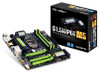 |
View all Gigabyte G1.Sniper M5 manuals
Add to My Manuals
Save this manual to your list of manuals |
Page 29 highlights
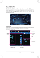
9) F_AUDIO (Front Panel Audio Header) The front panel audio header supports Intel High Definition audio (HD). You may connect your chassis front panel audio module to this header. Make sure the wire assignments of the module connector match the pin assignments of the motherboard header. Incorrect connection between the module connector and the motherboard header will make the device unable to work or even damage it. F_AUDIO(H) 9 1 10 2 Pin No. Definition 1 MIC2_L 2 GND F_PAN3EL(NH) MIC2_R 4 -ACZ_DET 5 LINE2_R 6 GND 7 FAUDIO_JD 8 No Pin 9 LINE2_L 10 GND Some chassis provide a front panel audio module that has separated connectors on each wire inDsBte_PaOdRoTf a single plug. For informaBtIiOoSnSawbitcohuetr (cXo5n8An-eOcCt)ing the front panel audio module that has different wire assignments, please contac1 t the chassis manufacturer. M_SATA F_PANEL (H61M-D2) DIP 1 23 1 DIP 1 234 DIP 1 23 1 DIP 1 23 1 F_USB30 10) F_USVBolt3ag0e(mUeaSsuBrem3e.0nt/m2o.0dulHe(Xe5a8dA-eOrC)) F_AUDIO(H) The header conforms to USB 3.0/2.0 specifiPcWaMtioSnwitacnh d(X5c8aAn-OpCr)ovide two USB ports. For purchasing the optional 3.5" front panel that provides two USB 3.0/2.0 ports, please contact the local dealer. ACFP_IP_CANPTEL(NH) (GA-IVB) PCIe power connector (SATA)(X58A-OC)20 DIP Pin No. Definition 1 23 1 VBUS 1 2 SSRX1- Pin No. Definition 11 D2+ 12 D2- SMB_CPT (GA-IVB) 3 SSRX1+ 13 GND 4 GND 14 SSTX2+ 5DB_PORSTSTX16 SSTX1+ 11 10 7 GND 8 D1- 9 D1+ 15 SSTXB2IO- S Switcher (X58A-OC) 16 GND 1 1 CLR_CMOS CI 17 SSRX2+ DIS_ME 18 SSRX219 VBUS GP15M__CSPATTA (GA-IVB) 10 NC 20 No Pin Voltage measurement points(G1.Sniper 3)Only thTweP/hMUouSsBiBnIOg pSoSrwtsitcrhoeru(tSeWd4t)o the Voltage measurement module(X58A-OC) F_USPBC3Ie0Choentarodl e(Zr87cXa-nUPs7u) pport thAeTXO_N12/VO_F2XF3Charge2 funPWctMioSnw. itch XDP_CPU (X58A-OC)XDP_PCH (GA-IVB) DIP 1 23 1 1 23 DIP DIP 1 234 DIP 1 234 Prior to installing the USB front panel, be sure to turn off your computer and unplug the power cDoIPrd DIP from the power outlet to prevent damage to the USB front panel. 1 23 1 234 PCIe power connector (SATA)(X58A-OC) F_USB3 (Front Panel) 1 DIP 1 23 1 - 29 - Hardware Installation Voltage measurement points(G1.Sniper 3) BIOS Switcher (SW4) PCIe Control (Z87X-UP7) ATX_ 4 IP
-
 1
1 -
2
-
3
-
4
-
5
-
6
-
7
-
8
-
9
-
10
-
11
-
12
-
13
-
14
-
15
-
16
-
17
-
18
-
19
-
20
-
21
-
22
-
23
-
 24
24 -
 25
25 -
 26
26 -
 27
27 -
 28
28 -
 29
29 -
 30
30 -
 31
31 -
 32
32 -
 33
33 -
 34
34 -
35
-
36
-
37
-
38
-
39
-
40
-
41
-
42
-
43
-
44
-
45
-
46
-
47
-
48
-
49
-
50
-
51
-
52
-
53
-
54
-
55
-
56
-
57
-
58
-
59
-
60
-
61
-
62
-
63
-
64
-
65
-
66
-
67
-
68
-
69
-
70
-
71
-
72
-
73
-
74
-
75
-
76
-
77
-
78
-
79
-
80
-
81
-
82
-
83
-
84
-
85
-
86
-
87
-
88
-
89
-
90
-
91
-
92
-
93
-
94
-
95
-
96
-
97
-
98
-
99
-
100
-
101
-
102
-
103
-
104
-
105
-
106
-
107
-
108
-
109
-
110
-
111
-
112
 |
 |
