Gigabyte GA-7TCSV4 Manual - Page 16
ATX_12V1/SSI_2X4P1/SSI_2X4P1, 2x4 12V Power Connector and 2x12 Main Power Connector
 |
View all Gigabyte GA-7TCSV4 manuals
Add to My Manuals
Save this manual to your list of manuals |
Page 16 highlights
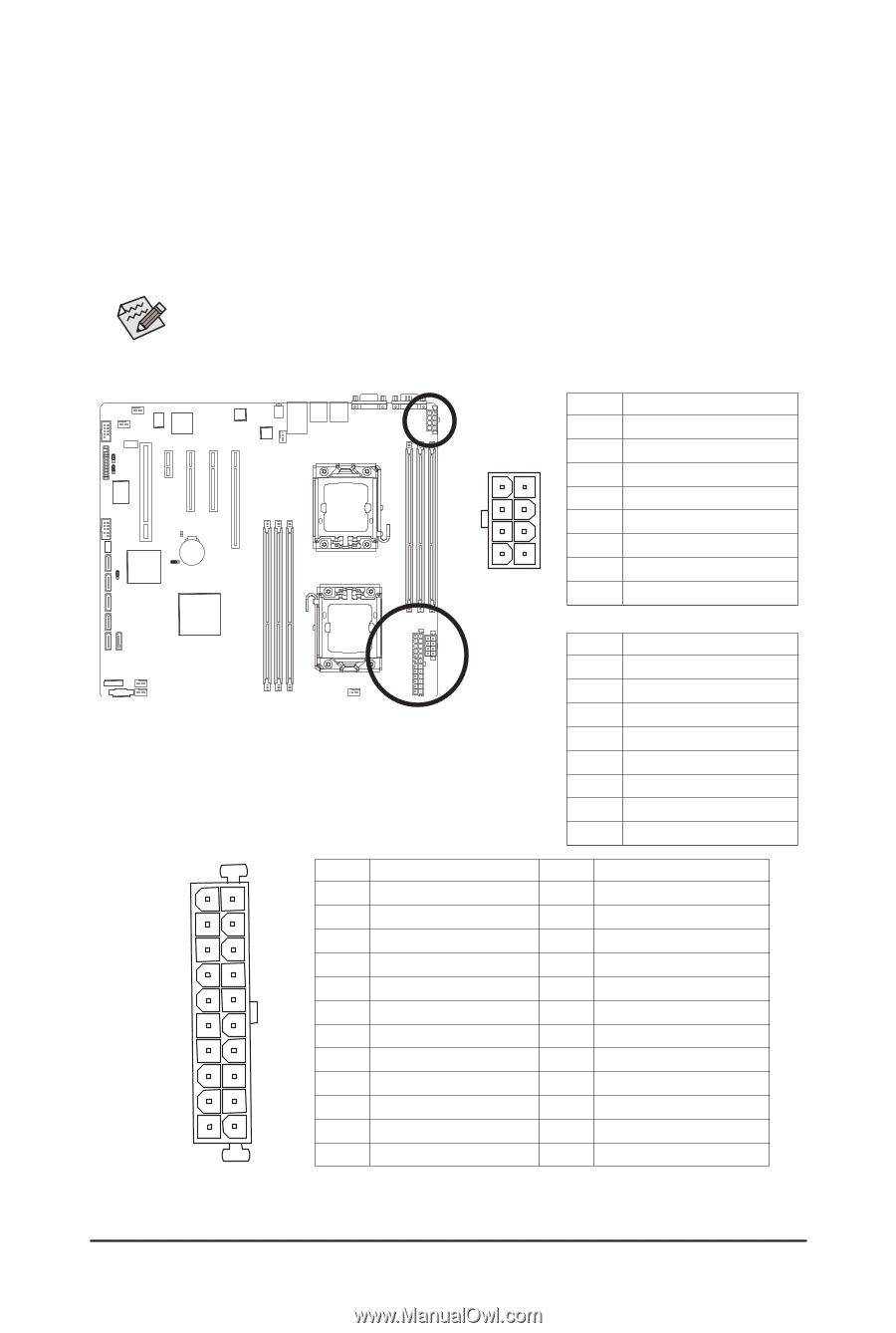
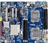
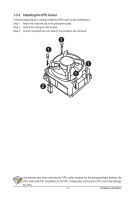
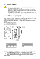
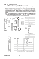
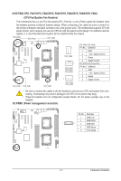
1/2/3) ATX_12V1/SSI_2X4P1/SSI_2X4P1 (2x4 12V Power Connector and 2x12 Main Power Connector) With the use of the power connector, the power supply can supply enough stable power to all the components on the motherboard. Before connecting the power connector, first make sure the power supply is turned off and all devices are properly installed. The power connector possesses a foolproof design. Connect the power supply cable to the power connector in the correct orientation. The 12V power connector mainly supplies power to the CPU. If the 12V power connector is not connected, the computer will not start. To meet expansion requirements, it is recommended that a power supply that can withstand high power consumption be used (500W or greater). If a power supply is used that does not provide the required power, the result can lead to an unstable or unbootable system. ATX_12V1 ATX 24 12 1 13 ATX_12V1 SSI_2X4P1 SSI_2X4P2 84 51 SSI_2X4P1 Pin No. Definition 1 GND 2 GND 3 GND 4 GND 5 P12V_DDR3_CPU1 6 P12V_DDR3_CPU1 7 P12V_CPU1 8 P12V_CPU1 SSI_2X4P2 Pin No. 1 2 3 4 5 6 7 8 Definition GND GND GND GND P12V_DDR3_CPU0 P12V_DDR3_CPU0 P12V_CPU0 P12V_CPU0 Pin No. 1 2 3 4 5 6 7 8 9 10 11 12 Definition Pin No. 3.3V 13 3.3V 14 GND 15 +5V 16 GND 17 +5V 18 GND 19 Power Good 20 5VSB (stand by +5V) 21 +12V 22 +12V (Only for 2x12-pin ATX) 23 3.3V (Only for 2x12-pin ATX) 24 Definition 3.3V -12V GND PS_ON (soft On/Off) GND GND GND -5V +5V +5V +5V (Only for 2x12-pin ATX) GND (Only for 2x12-pin ATX) Hardware Installation ATX_12V - 16 -
-
 1
1 -
2
-
3
-
4
-
5
-
6
-
7
-
8
-
9
-
10
-
 11
11 -
 12
12 -
 13
13 -
 14
14 -
 15
15 -
 16
16 -
 17
17 -
 18
18 -
 19
19 -
 20
20 -
 21
21 -
22
-
23
-
24
-
25
-
26
-
27
-
28
-
29
-
30
-
31
-
32
-
33
-
34
-
35
-
36
-
37
-
38
-
39
-
40
-
41
-
42
-
43
-
44
-
45
-
46
-
47
-
48
-
49
-
50
-
51
-
52
 |
 |