Gigabyte GA-7TCSV4 Manual - Page 20
F_PANEL1 Front Panel Header
 |
View all Gigabyte GA-7TCSV4 manuals
Add to My Manuals
Save this manual to your list of manuals |
Page 20 highlights
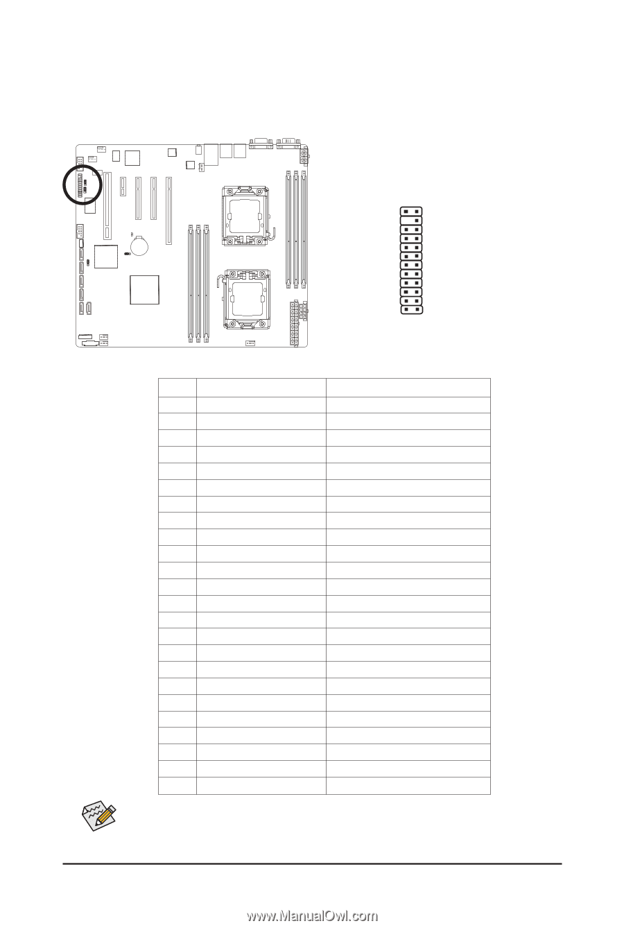
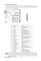
15) F_PANEL1 (Front Panel Header) Connect the power switch, reset switch, speaker, chassis intrusion switch/sensor and system status indicator on the chassis to this header according to the pin assignments below. Note the positive and negative pins before connecting the cables. 12 12 24 Pin No. Signal Name Definition 1 PWLED+ Power LED Signal anode (+) 2 5VSB 5V Stanndby Power 3 NC No Pin 4 ID_LED+ ID LED Signal anode (+) 5 PWLED- Power LED Signal cathode(-) 6 ID_LED- ID LED Signal cathode(-) 7 HD+ Hard Disk LED Signal anode (+) 8 F_SYSRDY System Front board LED Signal 9 HD- (GND) Ground 10 SYS_STATUS- System Status LED Signal cathode(-) 11 PWB+ Power Button Signal anode (+) 12 L1_ACT LAN1 active LED Signal 13 PWB+_GND Ground 14 L1_LINK- LAN1 Link LED Signal cathode(-) 15 RST_BTN+ Reset button Signal anode (+) 16 SENSOR_SDA SMBus Data Signal 17 RST_BTN_GND Ground 18 SENSOR_SCL SMBus Clock Signal 19 ID_SW+ ID Switch Signal anode (+) 20 CASE_OPEN- Chassis intrusion Signal cathode(-) 21 ID_SW (GND) Ground 22 L2_ACT LAN2 active LED Signal 23 NMI_SW- NMI switch Signal cathode(-) 24 L2_LINK- LAN2 Link LED Signal cathode(-) The front panel design may differ by chassis. A front panel module mainly consists of power switch, reset switch, power LED, hard drive activity LED, speaker and etc. When connecting your chassis front panel module to this header, make sure the wire assignments and the pin assign- ments are matched correctly. Hardware Installation - 20 -
-
 1
1 -
2
-
3
-
4
-
5
-
6
-
7
-
8
-
9
-
10
-
11
-
12
-
13
-
14
-
 15
15 -
 16
16 -
 17
17 -
 18
18 -
 19
19 -
 20
20 -
 21
21 -
 22
22 -
 23
23 -
 24
24 -
 25
25 -
26
-
27
-
28
-
29
-
30
-
31
-
32
-
33
-
34
-
35
-
36
-
37
-
38
-
39
-
40
-
41
-
42
-
43
-
44
-
45
-
46
-
47
-
48
-
49
-
50
-
51
-
52
 |
 |