Gigabyte GA-8I845GVM-775 Manual - Page 19
F_AUDIO Front Audio Connector
 |
View all Gigabyte GA-8I845GVM-775 manuals
Add to My Manuals
Save this manual to your list of manuals |
Page 19 highlights
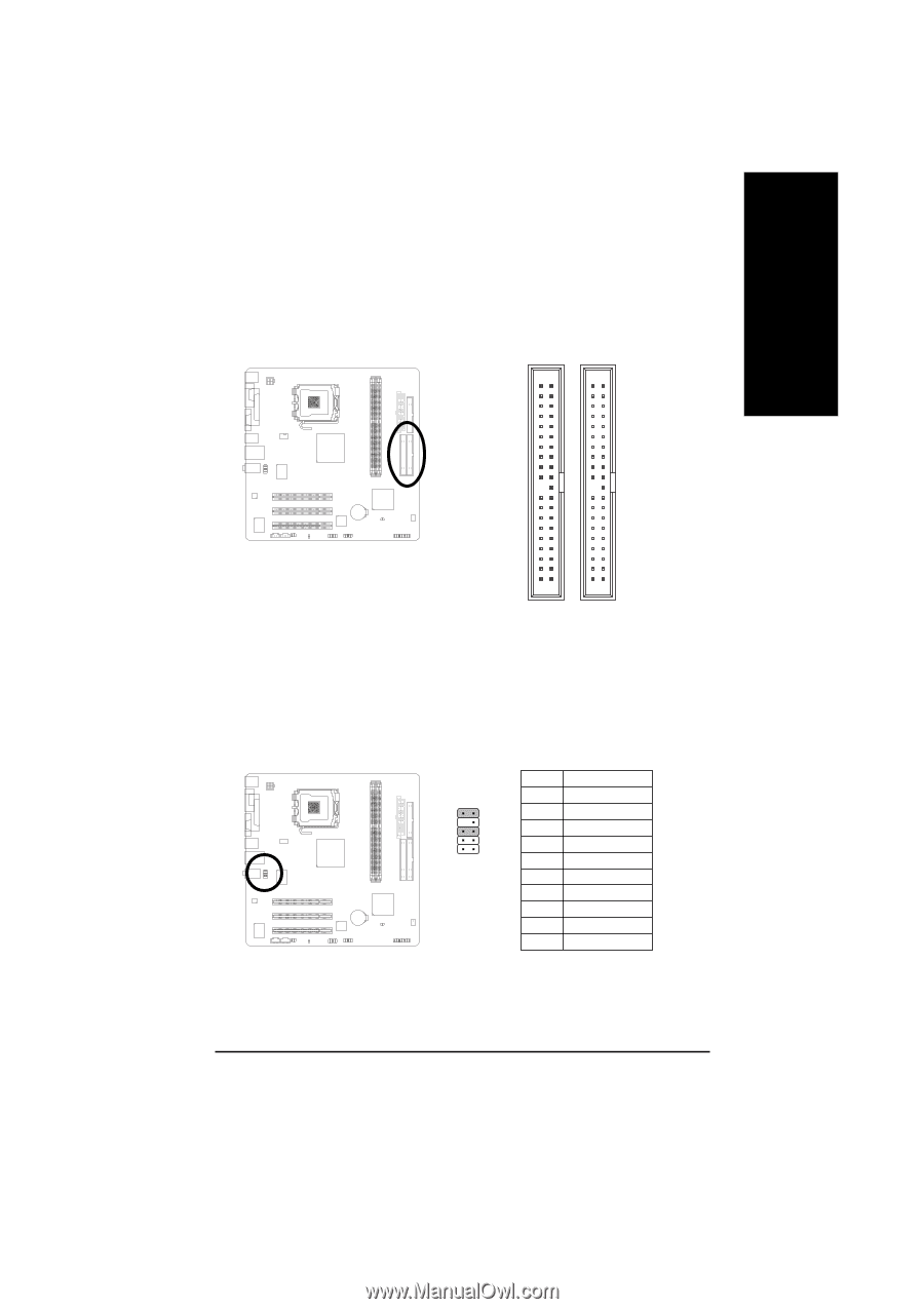
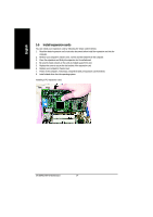
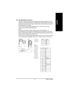
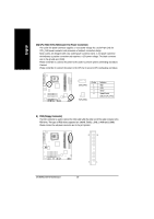
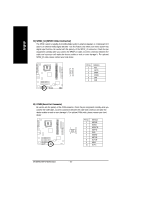
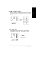
English 6) IDE1 / IDE2 (IDE1 / IDE2 Connector) An IDE device connects to the computer via an IDE connector. One IDE connector can connect to one IDE cable, and the single IDE cable can then connect to two IDE devices (hard drive or optical drive). If you wish to connect two IDE devices, please set the jumper on one IDE device as Master and the other as Slave (for information on settings, please refer to the instructions located on the IDE device). 40 39 2 1 7) F_AUDIO (Front Audio Connector) Please make sure the pin assignments on the cable are the same as the pin assignments of the F_AUDIO connector on the motherboard. To find out if the chassis you are buying support front audio panel connector, please contact your dealer. If you want to use "Front Audio" connector, you must remove the jumpers on pin 5-6, 9-10. 10 9 2 1 Pin No. 1 2 3 4 5 6 7 8 9 10 Definition MIC GND MIC_BIAS Power Front Audio (R) Rear Audio (R) NC No Pin Front Audio (L) Rear Audio (L) - 19 - Hardware Installation
-
 1
1 -
2
-
3
-
4
-
5
-
6
-
7
-
8
-
9
-
10
-
11
-
12
-
13
-
 14
14 -
 15
15 -
 16
16 -
 17
17 -
 18
18 -
 19
19 -
 20
20 -
 21
21 -
 22
22 -
 23
23 -
 24
24 -
25
-
26
-
27
-
28
-
29
-
30
-
31
-
32
-
33
-
34
-
35
-
36
-
37
-
38
-
39
-
40
-
41
-
42
-
43
-
44
-
45
-
46
-
47
-
48
-
49
-
50
-
51
-
52
-
53
-
54
-
55
-
56
-
57
-
58
-
59
-
60
-
61
-
62
-
63
-
64
-
65
-
66
-
67
-
68
-
69
-
70
-
71
-
72
 |
 |