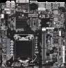
Gigabyte GA-H310TN User Manual - Page 12
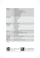
ATX_12V 2x2 12V Power Connector, 3 CPU_FAN/SYS_FAN Fan Headers, SATA3 0/1 SATA 6Gb/s Connectors
 |
View all Gigabyte GA-H310TN manuals
Add to My Manuals
Save this manual to your list of manuals |
Page 12 highlights
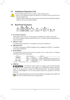
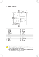
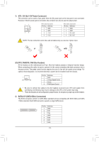
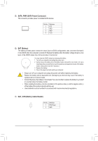
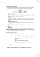
1) ATX_12V (2x2 12V Power Connector) This connector can be used to input power when the DC power jack on the rear panel is not connected. However, if the DC power jack is connected, this connector can only be used to output power. 13 24 When used to input power: Pin No. Definition 1 GND 2 GND 3 +12V 4 +12V When used to output power: Pin No. Definition 1 GND 2 GND 3 DC_OUT 4 DC_OUT NOTE: The two connectors cannot be used simultaneously as a source of power input. HDD LED RESET SW HDD LED RESET SW HDD LED RESET SW HDD LED RESET SW or with a r 2/3) CPU_FAN/SYS_FAN (Fan Headers) All fan headers on this motherboard are 4-pin. Most fan headers possess a foolproof insertion design. When connecting a fan cable, be sure to connect it in the correct orientation (the black connector wire is the ground wire). The speed control function requires the use of a fan with fan speed control design. For optimum heat dissipation, it is recommended that a system fan be installed inside the chassis. 1 CPU_FAN/SYS_FAN Pin No. 1 2 3 4 Definition GND Voltage Speed Control Sense PWM Speed Control •• Be sure to connect fan cables to the fan headers to prevent your CPU and system from overheating. Overheating may result in damage to the CPU or the system may hang. •• These fan headers are not configuration jumper blocks. Do not place a jumper cap on the headers. 4) SATA3 0/1 (SATA 6Gb/s Connectors) The SATA connectors conform to SATA 6Gb/s standard and are compatible with SATA 3Gb/s and SATA 1.5Gb/s standard. Each SATA connector supports a single SATA device. Pin No. Definition 1 GND 7 1 2 TXP 3 TXN 4 GND 5 RXN 6 RXP 7 GND - 12 - PORT PORT
-
 1
1 -
2
-
3
-
4
-
5
-
6
-
 7
7 -
 8
8 -
 9
9 -
 10
10 -
 11
11 -
 12
12 -
 13
13 -
 14
14 -
 15
15 -
 16
16 -
 17
17 -
18
-
19
-
20
-
21
-
22
-
23
-
24
-
25
-
26
-
27
-
28
-
29
-
30
-
31
-
32
-
33
-
34
-
35
-
36
-
37
-
38
-
39
-
40
-
41
 |
 |
