Gigabyte GA-H310TN User Manual - Page 14
F_PANEL Front Panel Header, M2A M.2 Socket 3 Connector
 |
View all Gigabyte GA-H310TN manuals
Add to My Manuals
Save this manual to your list of manuals |
Page 14 highlights
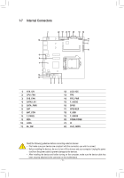
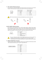
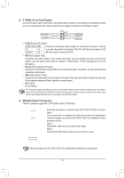
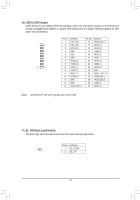
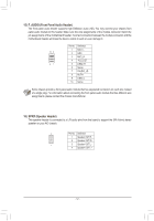
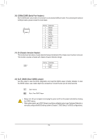
B SS 1 _S S 1 23 S B SS S SF U _ F_ F_ _ B S B_ B _S S_ _ B _U _ B F_USB3 F 8) F_PANEL (Front Panel Header) Connect the power switch, reset switch, and system status indicator on the chassis to this header according 1 23 1 1 23 1 to the pin assignments below. Note the positive and negative pins before connecting the cables. 1 23 1 Power Switch Power LED PWPW+ PLED- PLED+ 10 9 21 NC RES+ RES- HDHD+ Reset Switch Hard Drive Activity LED •• PLED (Power LED, Yellow): __ 3 System Status LED S0 On S3/S4/S5 Off Connects to the power status indicator on the chassis front panel. The LED is on when the system is operating. The LED is off when the system is in S3/ S4 sleep state or powered off (S5). •• PW (Power Switch, Red): Connects to the power switch on the chassis front panel. You may configure the way to turn off your system using the power switch (refer to Chapter 2, "BIOS Setup," "Power Management," for more information). •• HD (Hard Drive Activity LED, Blue): Connects to the hard drive activity LED on the chassis front panel. The LED is on when the hard drive is reading or writing data. •• RES (Reset Switch, Green): Connects to the reset switch on the chassis front panel. Press the reset switch to restart the computer if the computer freezes and fails to perform a normal restart. •• NC (Purple): No connection. The front panel design may differ by chassis. A front panel module mainly consists of power switch, reset switch, power LED, hard drive activity LED and etc. When connecting your chassis front panel module to this header, make sure the wire assignments and the pin assignments are matched correctly. 9) M2A (M.2 Socket 3 Connector) The M.2 connector supports M.2 SATA SSDs and M.2 PCIe SSDs. 80 Follow the steps below to correctly install an M.2 SSD in the M.2 connector. Step 1: Use a screw driver to unfasten the screw and nut from the motherboard. 60 Locate the proper mounting hole for the M.2 SSD to be installed and then screw the nut first. Step 2: Slide the M.2 SSD into the connector at an angle. Step 3: Press the M.2 SSD down and then secure it with the screw. 123 SS U B S_ B S S F _0 Select the proper hole for the M.2 SSD to be installed and refasten the screw and nut. - 14 -
-
 1
1 -
2
-
3
-
4
-
5
-
6
-
7
-
8
-
 9
9 -
 10
10 -
 11
11 -
 12
12 -
 13
13 -
 14
14 -
 15
15 -
 16
16 -
 17
17 -
 18
18 -
 19
19 -
20
-
21
-
22
-
23
-
24
-
25
-
26
-
27
-
28
-
29
-
30
-
31
-
32
-
33
-
34
-
35
-
36
-
37
-
38
-
39
-
40
-
41
 |
 |
