Gigabyte GA-H310TN User Manual - Page 18
SPEAKER Buzzer Header, F_USB USB 2.0/1.1 Header, Prior to installing the USB bracket
 |
View all Gigabyte GA-H310TN manuals
Add to My Manuals
Save this manual to your list of manuals |
Page 18 highlights
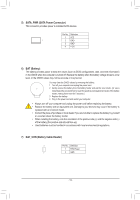
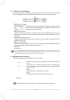
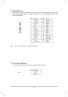
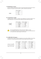
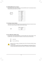
23 B S_ B SS S_ F_ _ 17) SPEAKER (Buzzer Header) Connects to the buzzer on the chassis front panel. The system reports system startup status by issuing a beep code. One single short beep will be heard if no problem is detected at system startup. _ B S B_ B _S S_ _ B _U _ B F_USB3 F Pin No. Definition 1 VCC 2 NC 1 3 NC 4 SPK- 18) F_USB (USB 2.0/1.1 Header) The header conforms to USB 2.0/1.1 specification. Each USB header can provide two USB ports via an optional USB bracket. For purchasing the optional USB bracket, please contact the local dealer. 2 10 1 9 Pin No. 1 2 3 4 5 Definition Power (5V) Power (5V) USB DXUSB DYUSB DX+ Pin No. 6 7 8 9 10 Definition USB DY+ GND GND No Pin NC 1 23 1 1 23 1 1 23 •• Do not plug the IEEE 1394 bracket (2x5-pin) cable into the USB 2.0/1.1 header. 1 •• Prior to installing the USB bracket, be sure to turn off your computer and unplug the power cord from the power outlet to prevent damage to the USB bracket. __ 3 _ _B U _ B SS 1 _S S 1 23 F_ B SS S SF F_ U S3 S_ B_ S 19) F_USB30 (USB 3.0/2.0 Header) The header conforms to USB 3.0 and USB 2.0 specification and can provide two USB ports. For purchasing the optional 3.5" front panel that provides two USB 3.0/2.0 ports, please contact the local dealer. Pin No. Definition Pin No. Definition Pin No. Definition 1 VBUS 8 D1- 15 SSTX2- 1 10 2 SSRX1- 9 D1+ 16 GND 3 SSRX1+ 10 NC 17 SSRX2+ 4 GND 11 D2+ 18 SSRX2- 20 11 5 SSTX1- 12 D2- 19 VBUS 6 SSTX1+ 13 GND 20 No Pin 7 GND 14 SSTX2+ - 18 - F_USB30
-
 1
1 -
2
-
3
-
4
-
5
-
6
-
7
-
8
-
9
-
10
-
11
-
12
-
 13
13 -
 14
14 -
 15
15 -
 16
16 -
 17
17 -
 18
18 -
 19
19 -
 20
20 -
 21
21 -
 22
22 -
 23
23 -
24
-
25
-
26
-
27
-
28
-
29
-
30
-
31
-
32
-
33
-
34
-
35
-
36
-
37
-
38
-
39
-
40
-
41
 |
 |
