Gigabyte GA-P55A-UD4P Manual - Page 44
Profile DDR Voltage, Channel Interleaving, CAS Latency Time
 |
UPC - 818313009081
View all Gigabyte GA-P55A-UD4P manuals
Add to My Manuals
Save this manual to your list of manuals |
Page 44 highlights
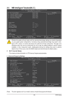
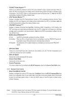
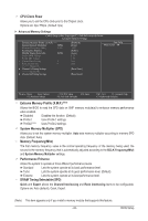
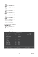
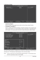
Profile DDR Voltage When using a non-XMP memory module or Extreme Memory Profile (X.M.P.) is set to Disabled, this item will display as 1.5V. When Extreme Memory Profile (X.M.P.) is set to Profile1 or Profile2, this item will display the value based on the SPD data on the XMP memory. Profile QPI Voltage The value displayed here is dependent on the CPU being used. Channel Interleaving Options are: Auto (default), 1~6. Rank Interleaving Options are: Auto (default), 1~4. >>>>> Channel A/B Timing Settings CMOS Setup Utility-Copyright (C) 1984-2009 Award Software Channel A Timing Settings >>>>> Channel A Standard Timing Control x CAS Latency Time 7 x tRCD 7 x tRP 7 x tRAS 20 >>>>> Channel A Advanced Timing Control x tRC 28 x tRRD 4 x tWTR 5 x tWR 10 x tWTP 21 x tWL 7 x tRFC 60 x tRTP 5 x tFAW 16 x Command Rate (CMD) 1 >>>>> Channel A Misc Timing Control x B2B CAS Delay - x Round Trip Latency 36 Auto Auto Auto Auto Auto Auto Auto Auto Auto Auto Auto Auto Auto Auto Auto Auto Item Help Menu Level Move Enter: Select F5: Previous Values +/-/PU/PD: Value F10: Save F6: Fail-Safe Defaults ESC: Exit F1: General Help F7: Optimized Defaults >>>>> Channel A/B Standard Timing Control CAS Latency Time Options are: Auto (default), 6~15. tRCD Options are: Auto (default), 1~15. tRP Options are: Auto (default), 1~15. tRAS Options are: Auto (default), 1~31. >>>>> Channel A/B Advanced Timing Control tRC Options are: Auto (default), 1~63. tRRD Options are: Auto (default), 1~7. BIOS Setup - 44 -
-
 1
1 -
2
-
3
-
4
-
5
-
6
-
7
-
8
-
9
-
10
-
11
-
12
-
13
-
14
-
15
-
16
-
17
-
18
-
19
-
20
-
21
-
22
-
23
-
24
-
25
-
26
-
27
-
28
-
29
-
30
-
31
-
32
-
33
-
34
-
35
-
36
-
37
-
38
-
 39
39 -
 40
40 -
 41
41 -
 42
42 -
 43
43 -
 44
44 -
 45
45 -
 46
46 -
 47
47 -
 48
48 -
 49
49 -
50
-
51
-
52
-
53
-
54
-
55
-
56
-
57
-
58
-
59
-
60
-
61
-
62
-
63
-
64
-
65
-
66
-
67
-
68
-
69
-
70
-
71
-
72
-
73
-
74
-
75
-
76
-
77
-
78
-
79
-
80
-
81
-
82
-
83
-
84
-
85
-
86
-
87
-
88
-
89
-
90
-
91
-
92
-
93
-
94
-
95
-
96
-
97
-
98
-
99
-
100
-
101
-
102
-
103
-
104
-
105
-
106
-
107
-
108
-
109
-
110
-
111
-
112
-
113
-
114
-
115
-
116
-
117
-
118
-
119
-
120
-
121
-
122
-
123
-
124
-
125
-
126
-
127
-
128
-
129
-
130
-
131
-
132
-
133
-
134
-
135
-
136
 |
 |
