Gigabyte GA-P55A-UD4P Manual - Page 95
Configuring JMB362 SATA Controller, A. Installing SATA hard drives in your computer
 |
UPC - 818313009081
View all Gigabyte GA-P55A-UD4P manuals
Add to My Manuals
Save this manual to your list of manuals |
Page 95 highlights
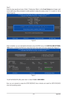
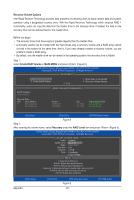
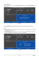
5-1-2 Configuring JMB362 SATA Controller A. Installing SATA hard drive(s) in your computer Attach one end of the SATA signal cable to the rear of the SATA hard drive and the other end to available SATA port on the motherboard. The JMB362 SATA controller controls the eSATA ports on the back panel. Then connect the power connector from your power supply to the hard drive. B. Configuring SATA controller mode in BIOS Setup Make sure to configure the SATA controller mode correctly in system BIOS Setup. Step 1: Turn on your computer and press to enter BIOS Setup during the POST (Power-On Self-Test). Make sure eSATA Controller under the Integrated Peripherals menu is enabled (Figure 1). To create RAID, set eSATA Ctrl Mode to RAID. CMOS Setup Utility-Copyright (C) 1984-2009 Award Software Integrated Peripherals PCH SATA Control Mode SATA Port0-3 Native Mode USB Controllers USB Legacy Function USB Storage Function Turbo SATA3/USB 3.0 Azalia Codec Onboard H/W 1394 Onboard H/W LAN1 Onboard H/W LAN2 j Green LAN } SMART LAN1 } SMART LAN2 j Onboard LAN1 Boot ROM Onboard LAN2 Boot ROM j Onboard IDE Controller eSATA Controller eSATA Ctrl Mode GSATA Controller [IDE] [Enabled] [Enabled] [Enabled] [Enabled] [Disabled] [Auto] [Enabled] [Enabled] [Enabled] [Disabled] [Press Enter] [Press Enter] [Disabled] [Disabled] [Enabled] [Enabled] [RAID] [Enabled] Item Help Menu Level Move Enter: Select F5: Previous Values +/-/PU/PD: Value F10: Save F6: Fail-Safe Defaults ESC: Exit F1: General Help F7: Optimized Defaults Figure 1 Step 2: Save changes and exit BIOS Setup. j Only for GA-P55A-UD4P. The BIOS Setup menus described in this section may differ from the exact settings for your motherboard. The actual BIOS Setup menu options you will see shall depend on the motherboard you have and the BIOS version. - 95 - Appendix
-
 1
1 -
2
-
3
-
4
-
5
-
6
-
7
-
8
-
9
-
10
-
11
-
12
-
13
-
14
-
15
-
16
-
17
-
18
-
19
-
20
-
21
-
22
-
23
-
24
-
25
-
26
-
27
-
28
-
29
-
30
-
31
-
32
-
33
-
34
-
35
-
36
-
37
-
38
-
39
-
40
-
41
-
42
-
43
-
44
-
45
-
46
-
47
-
48
-
49
-
50
-
51
-
52
-
53
-
54
-
55
-
56
-
57
-
58
-
59
-
60
-
61
-
62
-
63
-
64
-
65
-
66
-
67
-
68
-
69
-
70
-
71
-
72
-
73
-
74
-
75
-
76
-
77
-
78
-
79
-
80
-
81
-
82
-
83
-
84
-
85
-
86
-
87
-
88
-
89
-
 90
90 -
 91
91 -
 92
92 -
 93
93 -
 94
94 -
 95
95 -
 96
96 -
 97
97 -
 98
98 -
 99
99 -
 100
100 -
101
-
102
-
103
-
104
-
105
-
106
-
107
-
108
-
109
-
110
-
111
-
112
-
113
-
114
-
115
-
116
-
117
-
118
-
119
-
120
-
121
-
122
-
123
-
124
-
125
-
126
-
127
-
128
-
129
-
130
-
131
-
132
-
133
-
134
-
135
-
136
 |
 |