Gigabyte GA-P55A-UD4P Manual - Page 55
eSATA Ctrl Mode JMB362 Chip, eSATA Connectors, GSATA Ctrl Mode Marvell 9128 Chip
 |
UPC - 818313009081
View all Gigabyte GA-P55A-UD4P manuals
Add to My Manuals
Save this manual to your list of manuals |
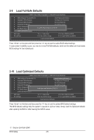
Page 55 highlights
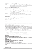
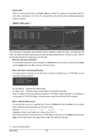
Onboard LAN1/LAN2 j Boot ROM Allows you to decide whether to activate the boot ROM integrated with the onboard LAN chip. (Default: Disabled) Onboard IDE Controller (IT8213 Chip) Enables or disables the IDE controller integrated in the IT8213 chip. (Default: Enabled) eSATA Controller (JMB362 Chip, eSATA Connectors) Enables or disables the SATA controller integrated in the JMB362 chip. (Default: Enabled) eSATA Ctrl Mode (JMB362 Chip, eSATA Connectors) Enables or disables RAID for the SATA controller integrated in the JMB362 chip or configures the SATA controller to AHCI mode. IDE Disables RAID for the SATA controller and configures the SATA controller to IDE mode. (Default) AHCI Configures the SATA controller to AHCI mode. Advanced Host Controller Interface (AHCI) is an interface specification that allows the storage driver to enable advanced Serial ATA features such as Native Command Queuing and hot plug. RAID Enables RAID for the SATA controller. GSATA Controller (Marvell 9128 Chip, GSATA3_6/7 Connectors) Enables or disables the SATA controller integrated in the Marvell 9128 chip. (Default: Enabled) GSATA Ctrl Mode (Marvell 9128 Chip, GSATA3_6/7 Connectors) Allows you to decide whether to configure the SATA controller integrated in the Marvell 9128 chip to AHCI mode. IDE Configures the SATA controller to IDE mode. (Default) AHCI Configures the SATA controller to AHCI mode. Advanced Host Controller Interface (AHCI) is an interface specification that allows the storage driver to enable advanced Serial ATA features such as Native Command Queuing and hot plug. GSATA RAID Configuration (Marvell 9128 Chip, GSATA3_6/7 Connectors) Allows you to configure RAID for the Marvell 9128 SATA controller. Refer to Chapter 5, "Configuring SATA Hard Drive(s)," for instructions on configuring a RAID array. Onboard Serial Port 1 Enables or disables the first serial port and specifies its base I/O address and corresponding interrupt. Options are: Auto, 3F8/IRQ4 (default), 2F8/IRQ3, 3E8/IRQ4, 2E8/IRQ3, Disabled. Onboard Parallel Port Enables or disables the onboard parallel port (LPT) and specifies its base I/O address and corresponding interrupt. Options are: 378/IRQ7 (default), 278/IRQ5, 3BC/IRQ7, Disabled. Parallel Port Mode Selects an operating mode for the onboard parallel (LPT) port. Options are: SPP (Standard Parallel Port) (default), EPP (Enhanced Parallel Port), ECP (Extended Capabilities Port), ECP+EPP. j Only for GA-P55A-UD4P. - 55 - BIOS Setup
-
 1
1 -
2
-
3
-
4
-
5
-
6
-
7
-
8
-
9
-
10
-
11
-
12
-
13
-
14
-
15
-
16
-
17
-
18
-
19
-
20
-
21
-
22
-
23
-
24
-
25
-
26
-
27
-
28
-
29
-
30
-
31
-
32
-
33
-
34
-
35
-
36
-
37
-
38
-
39
-
40
-
41
-
42
-
43
-
44
-
45
-
46
-
47
-
48
-
49
-
 50
50 -
 51
51 -
 52
52 -
 53
53 -
 54
54 -
 55
55 -
 56
56 -
 57
57 -
 58
58 -
 59
59 -
 60
60 -
61
-
62
-
63
-
64
-
65
-
66
-
67
-
68
-
69
-
70
-
71
-
72
-
73
-
74
-
75
-
76
-
77
-
78
-
79
-
80
-
81
-
82
-
83
-
84
-
85
-
86
-
87
-
88
-
89
-
90
-
91
-
92
-
93
-
94
-
95
-
96
-
97
-
98
-
99
-
100
-
101
-
102
-
103
-
104
-
105
-
106
-
107
-
108
-
109
-
110
-
111
-
112
-
113
-
114
-
115
-
116
-
117
-
118
-
119
-
120
-
121
-
122
-
123
-
124
-
125
-
126
-
127
-
128
-
129
-
130
-
131
-
132
-
133
-
134
-
135
-
136
 |
 |