Gigabyte MP30-AR0 Manual - Page 10
Installing the Memory
 |
View all Gigabyte MP30-AR0 manuals
Add to My Manuals
Save this manual to your list of manuals |
Page 10 highlights
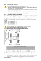
1-3 Installing the Memory 1-3-1 Read the following guidelines before you begin to install the memory: • Make sure that the motherboard supports the memory. It is recommended that memory of the same capacity, brand, speed, and chips be used. • Always turn off the computer and unplug the power cord from the power outlet before installing the memory to prevent hardware damage. • Memory modules have a foolproof design. A memory module can be installed in only one direction. If you are unable to insert the memory, switch the direction. Four Channel Memory Configuration This motherboard provides Eight DDR3 memory sockets and supports Four Channel Technology. After the memory is installed, the BIOS will automatically detect the specifications and capacity of the memory. Enabling Four Channel memory mode will be four times of the original memory bandwidth. The eight DDR3 memory sockets are divided into four channels each channel has two memory sockets as following: Channel 1: DDR3_P0_A0, DDR3_P0_A1 Channel 2: DDR3_P0_B0, DDR3_P0_B1 Channel 3: DDR3_P0_C0, DDR3_P0_C1 Channel 4: DDR3_P0_D0, DDR3_P0_D1 When only one DIMM is used, it must be populated in memory slot0 first. Memory populated sequence must be followed with slot0/slot1. System will not boot normally with incorrect populated sequence. DIMM_P0_C0 DIMM_P0_C1 DIMM_P0_D0 DIMM_P0_D1 DIMM_P0_B1 DIMM_P0_B0 DIMM_P0_A1 DIMM_P0_A0 Slot Per Channel (SPC) and DIMM Per Channel (DPC) 1 Slot 1DPC A0 or C0 2 Slot 1DPC A0 + B0 or A0 + C0 2DPC A0 + A1 or C0 + C1 4 Slot 1DPC A0 + B0 +C0 +D0 2DPC A0 + A1 + B0 + B1 or A0 + A1 + C0 + C1 8 Slot 2DPC Insert Full Due to CPU limitations, read the following guidelines before installing the memory in Four Channel mode. 1. Four Channel mode cannot be enabled if only one DDR3 memory module is installed. 2. When enabling Four Channel mode with two or four memory modules, it is recommended that memory of the same capacity, brand, speed, and chips be used for optimum performance. Hardware Installation - 10 -
-
 1
1 -
2
-
3
-
4
-
 5
5 -
 6
6 -
 7
7 -
 8
8 -
 9
9 -
 10
10 -
 11
11 -
 12
12 -
 13
13 -
 14
14 -
 15
15 -
16
-
17
-
18
-
19
-
20
-
21
-
22
-
23
 |
 |
