Gigabyte MP30-AR0 Manual - Page 6
Description, CAUTION, 3 pins
 |
View all Gigabyte MP30-AR0 manuals
Add to My Manuals
Save this manual to your list of manuals |
Page 6 highlights
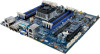
Item Code 1 LED_STA 2 USB2_MLAN 3 VGA1_COM1 4 SFP+_1_2 5 LAN1_2 6 SW_PWR 7 SW_ID 8 CPU_FAN 9 DIMM_P0_A0 10 DIMM_P0_A1 11 DIMM_P0_B0 12 DIMM_P0_B1 13 CPU0 14 P12V_AUX1 15 ATX1 16 SYS_FAN1 17 FP_1 18 SYS_FAN2 19 PMBUS 20 CLR_CMOS 21 SYS_FAN3 22 BP_1 23 CASE_OPEN 24 IPMB 25 SYS_FAN4 26 SATA_DOM0 27 SATA0/1/2/3 28 PCIE_2 29 BAT 30 PCIE_1 31 LED_BMC 32 DIMM_P0_C0 33 DIMM_P0_C1 34 DIMM_P0_D0 35 DIMM_P0_D1 Description System status LED BMC Management LAN port (top)/USB 2.0 ports (bottom) Serial port (top)/VGA port (bottom) 10G Fiber LAN ports LAN ports Power button/LED ID switch button/LED CPU fan connector Channel 1 slot 0 Channel 1 slot 1 Channel 2 slot 0 Channel 2 slot 1 ARM CPU 4 pin power connector 24 pin main power connector System fan connector#1 Front panel header (for Server system) System fan connector#2 PMBus header Clear CMOS jumper System fan connector#3 HDD back plane board header Case open intrusion alert header IPMB connector System fan connector#4 SATA port 3 DOM support jumper SATA3 6Gb/s connectors PCI Express x16 slot Battery socket PCI Express x16 slot BMC firmware readiness LED Channel 3 slot 0 Channel 3 slot 1 Channel 4 slot 0 Channel 4 slot 1 CAUTION! If a SATA type hard drive is connected to the motherboard, please ensure the jumper is closed and set to 2-3 pins (Default setting), in order to reduce any risk of hard disk damage. Please refer to Page 22 for SATA_DOM0 jumper setting instruction. - 6 -
-
 1
1 -
 2
2 -
 3
3 -
 4
4 -
 5
5 -
 6
6 -
 7
7 -
 8
8 -
 9
9 -
 10
10 -
 11
11 -
 12
12 -
13
-
14
-
15
-
16
-
17
-
18
-
19
-
20
-
21
-
22
-
23
 |
 |
