Gigabyte MP30-AR0 Manual - Page 17
SATA2/SATA3/SATA0/SATA1, SATA 6Gb/s Connectors/SATA3 Support SATA DOM Function, IPMB IPMB Connector
 |
View all Gigabyte MP30-AR0 manuals
Add to My Manuals
Save this manual to your list of manuals |
Page 17 highlights
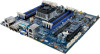
9) SATA2/SATA3/SATA0/SATA1 (SATA 6Gb/s Connectors/SATA3 Support SATA DOM Function) The SATA connectors conform to SATA 6Gb/s standard and are compatible with SATA 3Gb/s and 1.5Gb/s standard. Each SATA connector supports a single SATA device. Please see page 22 for SATA DOM jumper setting. 7 SATA2 SATA3 SATA0 SATA1 Normal Mode: 1 SATA DOM Mode: Pin No. 1 2 3 4 5 6 7 Definition GND TXP TXN GND RXN RXP GND Pin No. 1 2 3 4 5 6 7 Definition GND TXP TXN GND RXN RXP P5V • A RAID 0 or RAID 1 configuration requires at least two hard drives. If more than two hard drives are configured, the total number of hard drives must be an even number. • A RAID 10 configuration requires four hard drives. (Note) When a RAID configuration is built across the SATA 6Gb/s channels, the system performance of the RAID configuration may vary depends on the devices are connected. 10) IPMB (IPMB Connector) 1 Pin No. Definition 1 Clock 2 GND 3 3 Data - 17 - Hardware Installation
-
 1
1 -
2
-
3
-
4
-
5
-
6
-
7
-
8
-
9
-
10
-
11
-
 12
12 -
 13
13 -
 14
14 -
 15
15 -
 16
16 -
 17
17 -
 18
18 -
 19
19 -
 20
20 -
 21
21 -
 22
22 -
23
 |
 |
