Gigabyte MSH61DI Manual - Page 18
F_PANEL Front Panel Header
 |
View all Gigabyte MSH61DI manuals
Add to My Manuals
Save this manual to your list of manuals |
Page 18 highlights
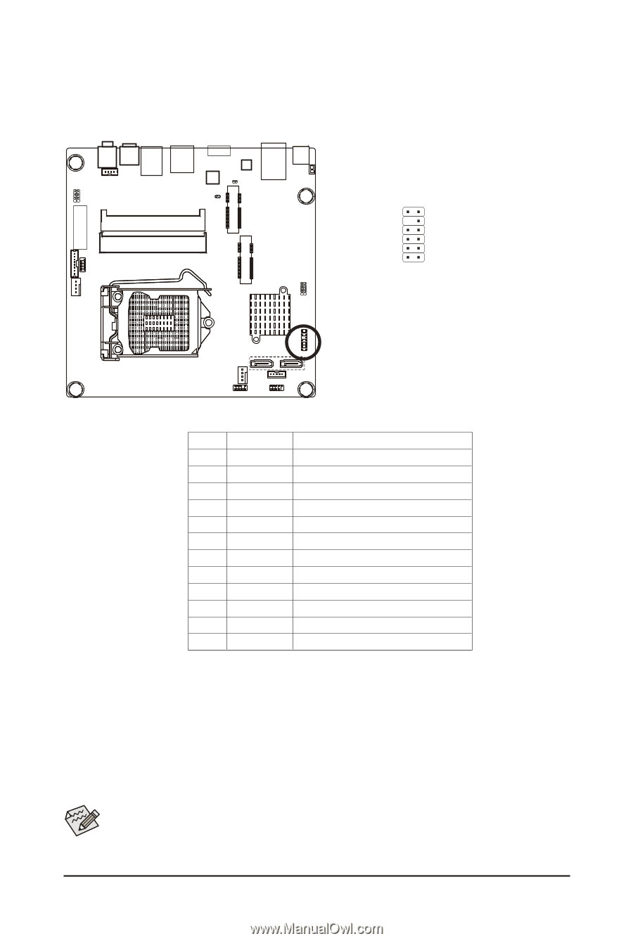
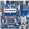
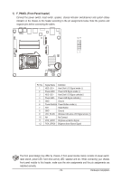
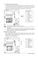
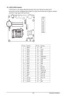
1) F_PANEL (Front Panel Header) Connect the power switch, reset switch, speaker, chassis intrusion switch/sensor and system status indicator on the chassis to this header according to the pin assignments below. Note the positive and negative pins before connecting the cables. 12 11 21 Pin No. 1 2 3 4 5 6 7 8 9 10 11 12 Signal Name Definition HDD LED + Hard Disk LED Signal anode (+) Power LED+ Power LED Signal anode (+) HDD LED - Hard Disk LED Signal cathode(-) Power LED- Power LED Signal cathode(-) GND Ground Power Switch+ Power Button anode (+) RST Reset Button GND Ground LED_WLAN Wireless LAN active LED Signal anode (+) NA No Connect PCH_GPIO1 Brigtness up Button Signal PCH_GPIO6 Brigtness down Button Signal The front panel design may differ by chassis. A front panel module mainly consists of power switch, reset switch, power LED, hard drive activity LED, speaker and etc. When connecting your chassis front panel module to this header, make sure the wire assignments and the pin assignments are matched correctly. - 18 - Hardware Installation
-
 1
1 -
2
-
3
-
4
-
5
-
6
-
7
-
8
-
9
-
10
-
11
-
12
-
 13
13 -
 14
14 -
 15
15 -
 16
16 -
 17
17 -
 18
18 -
 19
19 -
 20
20 -
 21
21 -
 22
22 -
 23
23 -
24
-
25
-
26
-
27
-
28
-
29
-
30
-
31
-
32
-
33
-
34
-
35
-
36
-
37
-
38
-
39
-
40
-
41
-
42
-
43
-
44
-
45
-
46
 |
 |