Gigabyte X570S AORUS MASTER User Manual - Page 21
Back Panel Connectors, USB 3.2 Gen 1 Port Q-Flash Plus Port
 |
View all Gigabyte X570S AORUS MASTER manuals
Add to My Manuals
Save this manual to your list of manuals |
Page 21 highlights
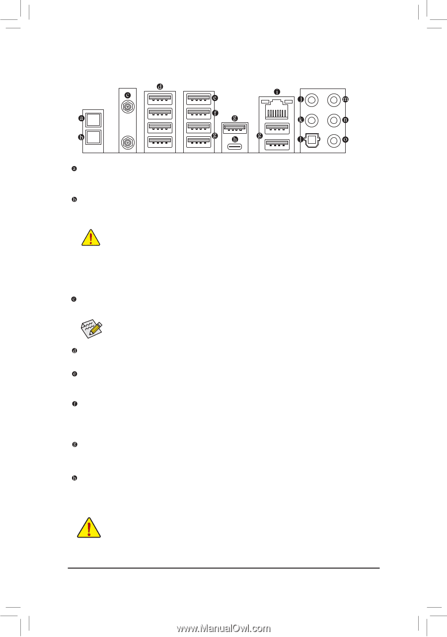
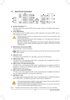
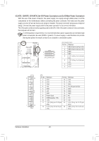
1-7 Back Panel Connectors Q-Flash Plus Button (Note) This button allows you to update the BIOS when the power connector is connected but the system is not powered on. Clear CMOS Button Use this button to clear the CMOS values (e.g. BIOS configuration) and reset the CMOS values to factory defaults when needed. •• Always turn off your computer and unplug the power cord from the power outlet before using the clear CMOS button. •• Do not use the clear CMOS button when the system is on, or the system may shutdown and data loss or damage may occur. •• After system restart, go to BIOS Setup to load factory defaults (select Load Optimized Defaults) or manually configure the BIOS settings (refer to Chapter 2, "BIOS Setup," for BIOS configurations). SMA Antenna Connectors (2T2R) Use this connector to connect an antenna. Tighten the antennas to the antenna connectors and then aim the antennas correctly for better signal reception. USB 2.0/1.1 Port The USB port supports the USB 2.0/1.1 specification. Use this port for USB devices. USB 3.2 Gen 1 Port The USB 3.2 Gen 1 port supports the USB 3.2 Gen 1 specification and is compatible to the USB 2.0 specification. Use this port for USB devices. USB 3.2 Gen 1 Port (Q-Flash Plus Port) The USB 3.2 Gen 1 port supports the USB 3.2 Gen 1 specification and is compatible to the USB 2.0 specification. Use this port for USB devices. Before using Q-Flash Plus , (Note) make sure to insert the USB flash drive into this port first. USB 3.2 Gen 2 Type-A Port (Red) The USB 3.2 Gen 2 port supports the USB 3.2 Gen 2 specification and is compatible to the USB 3.2 Gen 1 and USB 2.0 specification. Use this port for USB devices. USB Type-C® Port The reversible USB port supports the USB 3.2 Gen 2x2 specification and is compatible to the USB 3.2 Gen 2, USB 3.2 Gen 1, and USB 2.0 specifications. Use this port for USB devices. •• When removing the cable connected to a back panel connector, first remove the cable from your device and then remove it from the motherboard. •• When removing the cable, pull it straight out from the connector. Do not rock it side to side to prevent an electrical short inside the cable connector. (Note) To enable Q-Flash Plus function, refer to Chapter 5, "Unique Features," for more information. - 21 - Hardware Installation
-
 1
1 -
2
-
3
-
4
-
5
-
6
-
7
-
8
-
9
-
10
-
11
-
12
-
13
-
14
-
15
-
 16
16 -
 17
17 -
 18
18 -
 19
19 -
 20
20 -
 21
21 -
 22
22 -
 23
23 -
 24
24 -
 25
25 -
 26
26 -
27
-
28
-
29
-
30
-
31
-
32
-
33
-
34
-
35
-
36
-
37
-
38
-
39
-
40
-
41
-
42
-
43
-
44
-
45
-
46
-
47
-
48
-
49
-
50
-
51
-
52
-
53
-
54
-
55
-
56
-
57
-
58
-
59
-
60
-
61
-
62
-
63
-
64
-
65
-
66
-
67
-
68
-
69
-
70
-
71
-
72
-
73
-
74
-
75
-
76
-
77
-
78
-
79
-
80
-
81
-
82
-
83
-
84
-
85
-
86
-
87
-
88
-
89
-
90
-
91
-
92
-
93
-
94
-
95
-
96
-
97
-
98
-
99
-
100
-
101
-
102
-
103
-
104
-
105
-
106
-
107
-
108
 |
 |