Gigabyte X570S AORUS MASTER User Manual - Page 34
F_AUDIO Front Panel Audio Header, F_U32C USB Type-C, Header with USB 3.2 Gen 2 Support
 |
View all Gigabyte X570S AORUS MASTER manuals
Add to My Manuals
Save this manual to your list of manuals |
Page 34 highlights
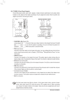
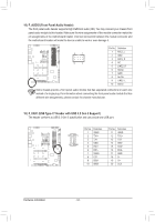
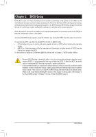
F_USB3 F _ _0 S _S 14) F_AUDIO (Front Panel A_ ud_Bio Header) _ S_ The front panel audio header supports High Definition audio (HD). You may connect your chassis front _ panel audio module to this header. Make sure the wire assignments of the module connector match the _F pin assignments of the motherboard header. Incorrect connection between the module connector and the motherboard header will make the device unable to work or even damage it. Pin No. Definition 1 MIC2_L 9 1 F_ U F_ 2 GND 3 MIC2_R 10 2 4 NC 5 LINE2_R 6 Sense _ S F_ 7 GND 8 No Pin 9 LINE2_L B B_ 10 Sense Some chassis provide a front panelBaSudSio module that has separated connectors on each wire insBt_ead of a single plug. For information about connecting the front panel audio module that has 1 different wire assignments, please contact the chassis manufacturer. _S 1 23 1 15) F_U32C (USB Type-C® Header with USBS 3.2 Gen 2 Support) The header conforms to USB 3.2 Gen 2 specification and can provide one USB port. _0 F F_ _3 U _ B 1 23 1 1 23 1 B_ USB 0_ B S3 S F_USB3 B SS S 1 23 F_USB30 3 10 11 1 20 Pin No. 1 2 3 4 5 6 7 8 9 10 U Definition VBUS TX1+ TX1GND RX1+ RX1VBUS CC1 SBU1 SBU2 Pin No. 11 12 13 14 15 16 17 18 19 20 __ 3 Definition VBUS TX2+ TX2GND RX2+ RX2GND DD+ CC2 S B_ B _S S_ _ B _U _ B S_ SF _ F_USB3 F Hardware Installation B_ S _S - 34 - _ _ _B _ S_
-
 1
1 -
2
-
3
-
4
-
5
-
6
-
7
-
8
-
9
-
10
-
11
-
12
-
13
-
14
-
15
-
16
-
17
-
18
-
19
-
20
-
21
-
22
-
23
-
24
-
25
-
26
-
27
-
28
-
 29
29 -
 30
30 -
 31
31 -
 32
32 -
 33
33 -
 34
34 -
 35
35 -
 36
36 -
 37
37 -
 38
38 -
 39
39 -
40
-
41
-
42
-
43
-
44
-
45
-
46
-
47
-
48
-
49
-
50
-
51
-
52
-
53
-
54
-
55
-
56
-
57
-
58
-
59
-
60
-
61
-
62
-
63
-
64
-
65
-
66
-
67
-
68
-
69
-
70
-
71
-
72
-
73
-
74
-
75
-
76
-
77
-
78
-
79
-
80
-
81
-
82
-
83
-
84
-
85
-
86
-
87
-
88
-
89
-
90
-
91
-
92
-
93
-
94
-
95
-
96
-
97
-
98
-
99
-
100
-
101
-
102
-
103
-
104
-
105
-
106
-
107
-
108
 |
 |
