Gigabyte Z590M GAMING X User Manual - Page 15
SATA3 0/1/2/3/4/5 SATA 6Gb/s Connectors, D_LED1/D_LED2 Addressable LED Strip Headers
 |
View all Gigabyte Z590M GAMING X manuals
Add to My Manuals
Save this manual to your list of manuals |
Page 15 highlights
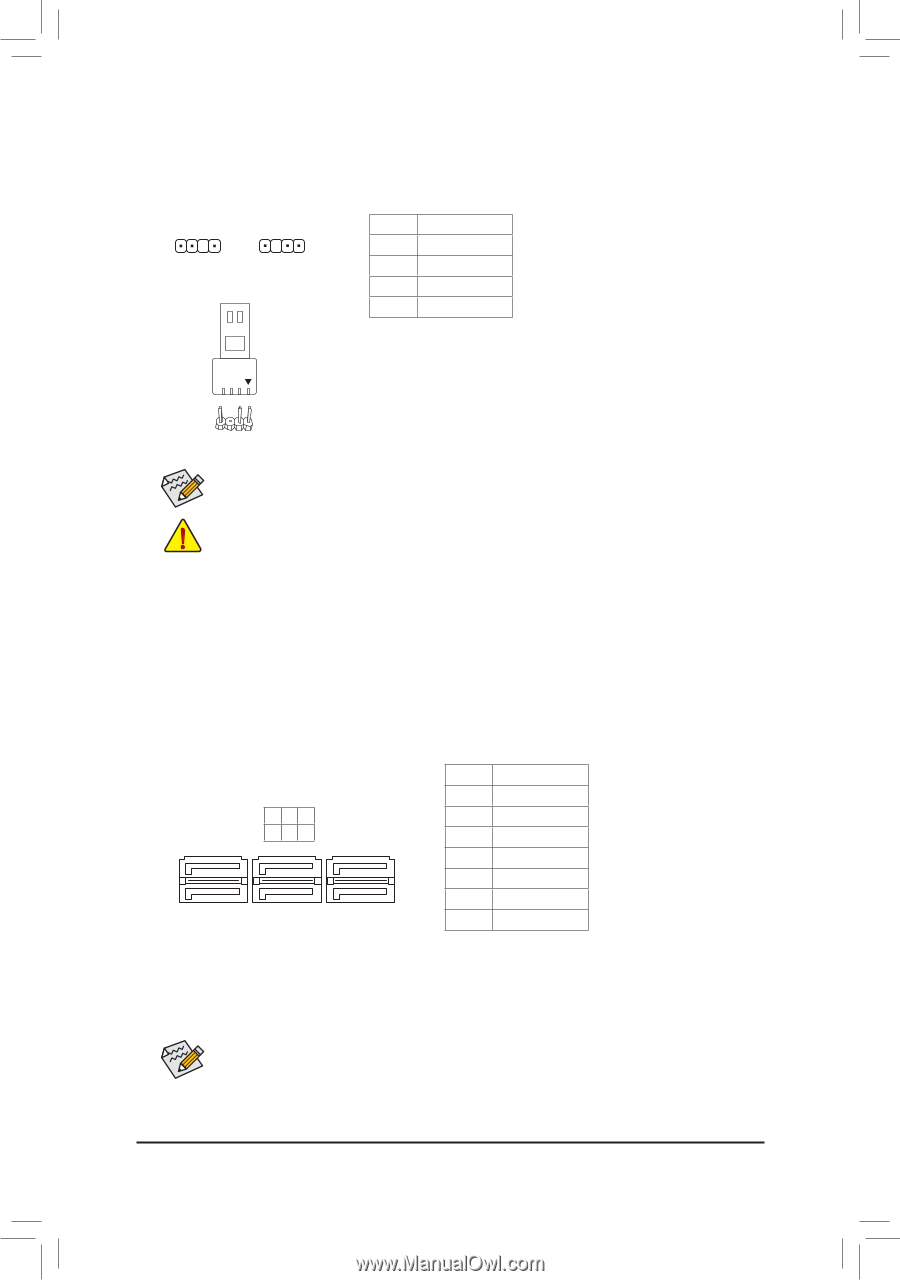
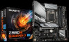
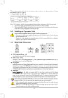
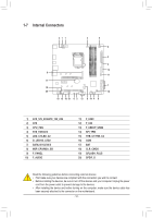
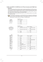
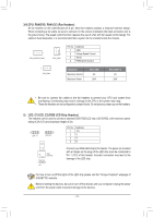
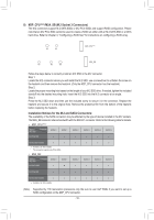
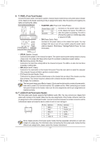
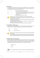
3 _ _B B S F_ B_ _S S_ _ B _U _ _3 _ F_USB3 F 6) D_LED1/D_LED2 (Addressable LED Strip Headers) The headers can be used to connect a standard 5050 addressable LED strip, with maximum power rating of 5A (5V) and maximum number of 1000 LEDs. B S_ 1 D_LED1 1 D_LED2 Pin No. 1 2 3 4 Definition V (5V) Data No Pin GND F_USB30 3 B_ Addressable LED Strip 1 Connect your addressable LED strip to the header. The power pin (marked with a triangle on the plug) of the LED strip must be connected to Pin 1 of the addressable LED strip header. Incorrect connection may lead to the damage of the LED strip. S F_ F_USB3 B For how to turn on/off the lights of the LED strip please visit the "Unique Features" webpage of GIGABYTE's website. Before installing the devices, be sure to turn off the devices and your computer. Unplug the power cord from the power outlet to prevent damage to the devices. F _0 _F _0 F B_ USB 0_ B _ 7) SATA3 0/1/2/3/4/5 (SATA 6Gb/s Connectors) The SATA connectors conform to SATA 6Gb/s standard and are compatible with SATA 3Gb/s and SATA 1.5Gb/s standard. Each SATA connector supports a single SATA device. The Intel® Chipset supports RAID 0, RAID 1, RAID 5, and RAID 10. Refer to Chapter 3, "Configuring a RAID Set," for instructions on configuring a RAID array. Pin No. Definition G.QBOFM G.QBOFM G.QBOF1M GND SATA3 5 3 1 420 2 TXP 3 TXN 4 GND 7 1 5 RXN 7 1 6 RXP 7 GND U B_ S_ S_ U To enable hot-plugging for the SATA ports, refer to Chapter 2, "BIOS Setup," "Settings\IO Ports\ SATA And RST Configuration," for more information. - 15 -
-
 1
1 -
2
-
3
-
4
-
5
-
6
-
7
-
8
-
9
-
 10
10 -
 11
11 -
 12
12 -
 13
13 -
 14
14 -
 15
15 -
 16
16 -
 17
17 -
 18
18 -
 19
19 -
 20
20 -
21
-
22
-
23
-
24
-
25
-
26
-
27
-
28
-
29
-
30
-
31
-
32
-
33
-
34
-
35
-
36
-
37
-
38
-
39
-
40
-
41
-
42
-
43
-
44
-
45
-
46
-
47
-
48
 |
 |