Gigabyte Z590M GAMING X User Manual - Page 19
COM Serial Port Header, THB_C1/THB_C2 Thunderbolt, Add-in Card Connectors
 |
View all Gigabyte Z590M GAMING X manuals
Add to My Manuals
Save this manual to your list of manuals |
Page 19 highlights
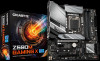
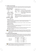
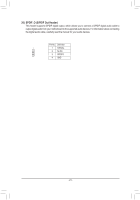
B_ B_ S_ S_ _U _ F B F_USB3 F 14) SPI_TPM (Trusted Platform Module Header) _ 0 You may connect an SPI TPM (Trusted Platform Module) to this header. U Pin No. Definition Pin No. Definition _B _ 1S1 _ 1 1 Data Output 7 Chip Select 2 Power (3.3V) 8 GND 3 No Pin _ F9 IRQ 12 2 4 NC 10 NC B_ 5 Data Input 11 NC 6 CLK 12 RST B_ F_USB3 F_USB30 3 _0 F USB 0_ B 15) THB_C1/THB_C2 (Thunderbolt™ Add-in Card Connectors) S F_ The connectors are used to connect to a GIGABYTE Thunderbolt™ add-in card. B_ USB 0_ B _ B_ 1 THB_C2 1 THB_C1 B_ S F_ B Supports a Thunderbolt™ add-in card. _ _3 U F_USB30 3 F_USB3 16) COM (Serial Port Header) The COM header can provide one serial port via an optional COM port cable. For purchasing the optional COM port cable, please contact the local dealer. B S F_ S _S B_ 9 1 _ 10 2 F_USB30 3 _ _B Pin No. 1 2 3 4 5 Definition NDCDNSIN NSOUT NDTRGND Pin No. 6 7 8 9 10 B_ _ Definition NDSRNRTSNCTSNRINo Pin S_ S _S _ _ _B _ SF _ S_ __ 3 S3 B SS S U S_ _ B _U _ B F_USB3 F - 19 -
-
 1
1 -
2
-
3
-
4
-
5
-
6
-
7
-
8
-
9
-
10
-
11
-
12
-
13
-
 14
14 -
 15
15 -
 16
16 -
 17
17 -
 18
18 -
 19
19 -
 20
20 -
 21
21 -
 22
22 -
 23
23 -
 24
24 -
25
-
26
-
27
-
28
-
29
-
30
-
31
-
32
-
33
-
34
-
35
-
36
-
37
-
38
-
39
-
40
-
41
-
42
-
43
-
44
-
45
-
46
-
47
-
48
 |
 |
