Harman Kardon A250 Owners Manual - Page 10
inconspicuous
 |
View all Harman Kardon A250 manuals
Add to My Manuals
Save this manual to your list of manuals |
Page 10 highlights
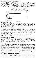
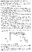
USING THE MODEL A-250 AS A CONVERSION AMPLIFIER FOR STEREO If you now own a basic amplifier, or an amplifier-preamplifier, you may utilize the Model A-250 for the second channel and control the entire stereo system with the A-250 preamplifiers. For this application the Model A-250 is connected in the manner described below, INSTALLATION PROCEDURE Connecting Your Speakers: Your two speakers should be matched if possible to obtain optimum results and should he placed 8 to 15 feet apart against one wall of your listening room. Corner placement is also quite acceptable. Facing the speakers straight out or slanting them slightly, will depend on your room size, acoustic effect and where you will be seated for listening. It may be necessary to experiment with speaker placement until best results are obtained. • Use any type wire to connect your speakers. Lamp cord is excellent and may be easily dressed around the molding for an inconspicuous and neat installation. Speaker Connection For Conversion Arrangement: Set the SEPARATE-PARALLEL switch located on the front chassis support apron directly behind the pilot light to the "PARALLEL" position and strap the appropriate Speaker Output terminals together. IMPORTANT: Whenever the SEPARATE-PARALLEL switch is in the "PARALLEL" position, the Speaker Output terminals must be strapped together, and conversely whenever the Speaker Output terminals are strapped together, the SEPARATE-PARALLEL switch must be in the "PARALLEL" position. Connect Speaker A (refer to Diagram E) to either 32 ohm terminal on the SPEAKER OUTPUT strip and the other lead to either A terminal. Now tie the two 32 ohm terminals together. The A and B terminals on both output strips have been strapped together at the factory, and should be left that way. If you are using an 8 ohm speaker, tie the two 16 ohm terminals together instead of the 32 ohm terminals as described. The SPEAKER SELECTOR switch on the front panel may be placed in any position since it is inoperative for this method of installation. Connect Speaker B to the "G" and 16 ohm speaker terminals on your other monaural amplifier. RIGHT SPEAKERS LEFT SPEAKERS O OO B 4 13 16 32 A B 4 8 IS 32 RIGHT SPE6A1K1ER SECOND AMPLIFIER 6 6 16 LEFT SPEAKER 1611 Diagram E Connecting Both Amplifiers For Stereo Operation: Connect a shielded lead not longer than 3 or 4 feet between the LEFT PREAMP OUT ;ack on the rear of the A-250 and the Aux or Tuner input on your other amplifier. IMPORTANT: Connect the AC power cord from your monaural amplifier to the AC convenience outlet on the rear of the Model A-250. The on/off switch on the A-250 will now control the power for both amplifiers.
-
 1
1 -
2
-
3
-
4
-
 5
5 -
 6
6 -
 7
7 -
 8
8 -
 9
9 -
 10
10 -
 11
11 -
 12
12 -
 13
13 -
 14
14 -
 15
15 -
16
 |
 |
