Harman Kardon A250 Owners Manual - Page 13
Function, Switch, Speaker, Selector, Rumble, Filter, Scratch, Equalization
 |
View all Harman Kardon A250 manuals
Add to My Manuals
Save this manual to your list of manuals |
Page 13 highlights
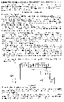
This switch has four positions. STEREO NORMAL enables the speakers to operate in the manner in which they are normally connected. STEREO REVERSE interchanges the channels so that the program source appearing at the left speaker now appears at the right and the program source appearing at the right speaker reverses to the left. MONAURAL RIGHT and MONAURAL LEFT can be utilized when the amplifier is used in stereo connection, but with a monaural program source such as an FM broadcast. Setting the MODE switch to RIGHT allows any program material being fed into the right stereo input to be reproduced by both speakers simultaneously. Setting the MODE switch to LEFT allows all program material being fed into the left stereo input to be reproduced by both speakers simultaneously. Under each of these conditions the combined power of both channels is available. Function Switch: The FUNCTION switch selects the desired type of program source and has five positions. AUX 1 and AUX 2 selects equipment connected to the auxiliary input jacks. TUNER selects your stereo tuner for operation and PHONO selects either your magnetic or ceramic stereo cartridge. TAPE HD selects your stereo tape deck. Speaker Selector Switch: In a stereo installation where more than one set of stereo speakers are installed (for example: one pair of speakers in the living room and one pair in the den) selection between the two systems is made by operating the two SPEAKER SELECTOR switches located on the front panel. To operate only System A, set the upper SPEAKER SELECTOR switch to "A" and the lower switch to "ONE". To operate only System B, set the upper SPEAKER SELECTOR switch to "B" and the lower speaker switch to "ONE". To operate both systems simultaneously, the upper speaker switch may remain in "A" or "B" and the lower SPEAKER SELECTOR switch must he set to "ALL". Rumble Filter Switch: At times, record changers, turntables, and even some FM stations produce an objectionable low frequency signal that is strong enough to be introduced into the sensitive playback system. Known as "Rumble" this undesirable signal can be eliminated by the special RUMBLE FILTER switch incorporated in the Model A-250. Whenever rumble is encountered, set the switch to "ON". Scratch Filter Switch: In the event of objectionable high frequency record scratch, throw the SCRATCH FILTER switch to "ON". This will roll off the higher frequencies. Equalization Switch: In order to assure good reproduction of the wide range of frequencies in music and to make necessary adjustments for the limitations of the recording technique, record manufacturers have found it necessary to modify the actual frequency response of the music while it is being recorded. Thus, to avoid overcutting and consequent distortion, a measured and deliberate reduction is effected in low frequency response by selecting a "turnover frequency" and by recording attenuated response below that point. To assure optimum signal-tonoise at the high frequency end when the record is played at home, the highs are deliberately exaggerated during the recording process. A measured and deliberate boost is effected above a certain frequency. This combination of deliberate exaggeration at the low and high ends of the frequency response can be expressed in a "recording curve". When the record is played a mirror image of that curve should he available so that the ideal "flat" response may be achieved.
-
 1
1 -
2
-
3
-
4
-
5
-
6
-
7
-
 8
8 -
 9
9 -
 10
10 -
 11
11 -
 12
12 -
 13
13 -
 14
14 -
 15
15 -
 16
16
 |
 |
