Harman Kardon AVR 645 Owners Manual - Page 24
In/outsetup
 |
View all Harman Kardon AVR 645 manuals
Add to My Manuals
Save this manual to your list of manuals |
Page 24 highlights
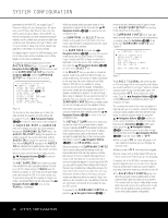
SYSTEM CONFIGURATION sor is pointing to the AUDIO AUTO POLL line, simply press the ‹/› Navigation Buttons D© so that OFF (rather than ON) is highlighted. When the desired auto-poll setting is entered, press the ⁄/¤ Navigation Button D© to move to the next line. When the cursor is at the VIDEO IN-PORT line, you are able to select an alternative to the default input setting for the video input associated with any source. For the Video 1 and Video 4 inputs, the factory default of AUTO will select either composite or Svideo, depending on which has an active signal. For the Video 2, Video 3 and DVD inputs, the AUTO setting will normally select the default component input, but if it is not in use, the system will revert to a composite or S-video output if either one is active. To have the AVR always look to a specific source connection when an input is selected, make certain that the on-screen cursor is pointing to the VIDEO IN-PORT line, and then press the ‹/› Navigation Buttons D© until the name of the desired input appears. The default setting for HDMI inputs is AUTO and normally need not be changed. However, in systems where the HDMI connection is used for multichannel audio only (e.g., HDMI 1.1), but the video connection is component, due to limitations on the video display, the setting here should be changed to COMPONENT. When the desired video input setting has been made, press the ⁄/¤ Navigation Buttons D© to move to the next line. If your system includes any sources that are equipped with Y/Pr/Pb component video outputs, the AVR 645 is able to switch them to send the proper signals to your video display. Each of the Component Video Inputs O is assigned to a default source, as shown in the table in the Appendix, but if you have connected your system differently than the factory settings, you may select any of the three inputs for any source except the HDMI inputs or the Tuner. If you do not need to change these defaults, press the ¤ Navigation Button D to go to the next setting. To change the Component Video assignment, first make certain that the cursor is pointing to the COMPONENT INPUT line on the menu screen, and then press the ‹/› Navigation Button D© until the desired input is highlighted. When the desired component input has been selected, press the ¤ Navigation Button D© to go to the next setting. At the VIDEO PROCESS line, you are able to select whether video format conversion is to be used with the input source being configured. If you do not need to change the setting, simply press the ⁄/¤ Navigation Buttons D© to continue. The default setting of V-CONVERSION will output the incoming video in one of the following ways, depending on the input source. • A standard-definition (480i) analog signal (composite, S-video or component) will be converted so that it is available as an HDMI signal at its input resolution, as well as at the standard composite, S-video or component analog video outputs. The signal will also be available at the record outputs. • An analog component high-definition signal will be output at its input resolution through the HDMI outputs and as an analog component signal, but not through the analog composite or S-video monitor or record outputs. • HDMI input signals, regardless of their resolution, will be output through the HDMI outputs only. The BYPASS setting will not apply any video conversion to the incoming video signal, but it will output it in one of the following ways, depending on the input source. • Analog signals (composite, S-video or component) will output only in the resolution and format that matches the input for both the main "Monitor" connection as well as for the record outputs. • HDMI input signals, regardless of their resolution, will be output through the HDMI outputs only. After any needed change to the video conversion setting has been made, press the ⁄/¤ Navigation Buttons D© to move to the next line. At the A/V SYNC DELAY line, you are able to enter a setting that delays the audio output slightly behind the video so that the loss of lip sync that may occur due to digital video processing in the transmission of a program, in the playback unit or in the display is corrected. This lack of lip sync is not a fault of the sources; rather, it is a by-product of video signal processing. In most cases, we recommend that the delay adjustment be made using the direct-access controls on the remote so that you may more accurately adjust the delay while viewing the on-screen image, following the instructions shown on page 32, but you may also make it here using the menu system. As the amount of delay needed may vary from one source to another, we strongly recommend that you adjust it for each input. To adjust the A/V sync delay time from the IN/OUT SETUP menu, make certain that the cursor is pointing to the A/V SYNC DELAY line, and then press the ‹/› Navigation Buttons D© until the desired amount of delay is applied so that the on-screen video matches the audio. When all configuration adjustments on this menu screen have been made, press the ⁄/¤ Navigation Buttons D© until the on-screen cursor is pointing to PAGE 2 and then press the Set Button pœ to move to the second screen of input/output settings. If all settings for input configuration are complete, press the ⁄/¤ Navigation Buttons D© until the on-screen cursor is pointing to MASTER MENU and then press the Set Button pœ to return to the main menu screen. The second page of the IN/OUT SETUP menu (Figure 3) allows you to further configure the AVR 645 for special custom features. * IN/OUT SETUP * ➔ VIDEO 4 COAXIAL 4 REC OUT HDMI LINK :IN OUT :IN OUT :ANALOG :ON OFF MASTER MENU PAGE 1 Figure 3 An exclusive Harman Kardon feature is the ability to switch the front-panel coaxial digital audio and analog audio/video jacks from their normal use as inputs to output connections so that portable recording devices may easily be connected. The front-panel analog Video 4 Jacks N are normally set as inputs for use with camcorders, video games and other portable audio/video products, but they may be switched to outputs. First, make certain that you are at the IN/OUT SETUP menu. Press the ¤ Navigation Buttons D© until the cursor is pointing to the VIDEO 4 line. Press the ‹/› Navigation Buttons D© so that the word OUT is highlighted. The Input/Output Status Indicator L between the S- and composite video jacks will turn red, indicating that the analog Video 4 jacks are now record outputs. On the AVR 645, the Coaxial 4 Digital Jack M is normally an input, but it may be switched to a digital output for use with digital recorders. To change the jack to an output, press the ⁄/¤ Navigation Buttons D© while the IN/OUT SETUP menu is on screen until the cursor is next to COAXIAL 4. Then press the ‹/› Navigation Buttons D© so that OUT is highlighted. The Input/Output Status Indicator L will then turn red, indicating that the jack is now a record output. NOTES: • A signal will be sent to this jack only when the input selected for use by the AVR 645 is digital. Digital signals will be passed through, regardless of their 24 SYSTEM CONFIGURATION
-
 1
1 -
2
-
3
-
4
-
5
-
6
-
7
-
8
-
9
-
10
-
11
-
12
-
13
-
14
-
15
-
16
-
17
-
18
-
 19
19 -
 20
20 -
 21
21 -
 22
22 -
 23
23 -
 24
24 -
 25
25 -
 26
26 -
 27
27 -
 28
28 -
 29
29 -
30
-
31
-
32
-
33
-
34
-
35
-
36
-
37
-
38
-
39
-
40
-
41
-
42
-
43
-
44
-
45
-
46
-
47
-
48
-
49
-
50
-
51
-
52
-
53
-
54
-
55
-
56
-
57
-
58
-
59
-
60
-
61
-
62
-
63
-
64
-
65
-
66
-
67
-
68
 |
 |
