Harman Kardon TD302 Owners Manual - Page 8
Recording, Operations
 |
View all Harman Kardon TD302 manuals
Add to My Manuals
Save this manual to your list of manuals |
Page 8 highlights
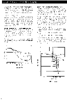
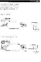
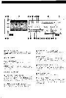
RECORDING OPERATIONS Tape Recording 1. Turn the volume control knob of the receiver to the minimum level and turn on the receiver. Then press the TD302 POWER switch. The POWER indicator lights up. 2. Press the EJECT button to open the CASSETTE COMPARTMENT door and carefully insert a cassette tape. Incorrect cassette insertion may cause a malfunction in door closing or recording. 3. Press the TAPE SELECTOR button corresponding tothe type of tape being used. 4. To record with the Dolby NR system, depress the DOLBY NR switch to the "on" position and select the "B"- or "C"-type with the DOLBY NR TYPE selector. The B-type indicator will i lluminate in green, or the C-type indicator in amber. 5. To record from an FM stereo tuner or receiver with the Dolby NR system, set the MPX FILTER switch to the "on" (out) position. This is not necessary if the tuner or receiver has 19kHz pilot cancell ing. 6. Press the RECORD and PAUSE buttons at the same time. The RECORD and PAUSE indicators i lluminate. The record level is accurately displayed on the PEAK LEVEL METERS. 7. Adjust the record level with the INPUT LEVEL control knob as per the instructions provided in the "Recording Level Adjustment" section on this page. 8. Adjust the INPUT BALANCE control knob if necessary. (Refer to CONTROLS AND FUNCTIONS on page 6.) 9. Press the COUNTER RESET button to reset the TAPE COUNTER indication to "000". 10. Press the PLAY button to start recording. The PAUSE indicator goes out. 11. Press the PAUSE button for temporarily stopping the tape. Press the PLAY button to restart recording. 12. Press the STOP button to stop recording. 13. Tape recording automatically stops when the end of the tape is reached and the record mode is cancelled. Cassette Tape and Corresponding Tape Selector Settings The table below shows several types of major brand tapes and the corresponding tape selector settings. Position LN CrO2 METAL MAXELL UDI * XLI XLI-S XLII MX XLII-S AD * SA * MA AD-S SA-X MA-R TDK AR AR -X SONY I HF-S HF-ES HF-PRO UCX UCX-S Metal-S Metal-ES AXIA (FUJI) PS-I GT-I GT-II DEMON DX -3 DX-4 HD-6 HD-S DX -M BASF PRO-I PRO-II PRO-IV Tapes with the mark (8) are the standard reference tapes. Recording Level Adjustment With the INPUT BALANCE control knob at 12 o'clock position, adjust the optimum record level by moving the INPUT LEVEL control knob while observing the PEAK LEVEL METER in order to meet the type of the tape to be recorded. •Make adjustment as described below when the sound level is relatively high. When using a metal tape. PEAK LEVEL METER LEFT dB RIGHT - 2I 0 -15 -10 -7 -2 5 -13 0 +1 +13 OC LEFT dB RIGHT Momentary illumination up to +5dB is allowable. When using chromium dioxide tape. PEAK LEVEL METER LEFT dB RIGHT - 20 -15 -10 -17 +13 -15 +8 LEFT de RIGHT From time to time illumination up to +1dB is allowable. When using a low noise tape. PEAK LEVEL METER LEFT LEFT dB - 20 -15 - 10 -7 -15 -13 +3 45 4-8 0B RIGHT RIGHT 00 Momentary illumination up to +3dB is allowable. •The following adjustments will cause excessive sound distortion or tape noise. Too high an input level setting (illumination up to +8dB). PEAK LEVEL METER LEFT dB RIGHT - 20 -15 - 10 -7 - 15 -3 +1 +13 +5 +8 OC LEFT de RIGHT A recording with excessive distortion will result. Too low an input level setting (peak illumination of less than 0dB). PEAK LEVEL METER LEFT Ime dB -20 -15 - 10 RIGHT INN oo= 00000 +1 +13 0 0 0 0 0= LEFT RIGHT A recording with excessive tape noise will result. 7
-
 1
1 -
2
-
 3
3 -
 4
4 -
 5
5 -
 6
6 -
 7
7 -
 8
8 -
 9
9 -
 10
10 -
 11
11
 |
 |
