Hayward EcoStar Technical Guide - Page 38
Make sure during reassembly to tighten these screws fully as - motor
 |
View all Hayward EcoStar manuals
Add to My Manuals
Save this manual to your list of manuals |
Page 38 highlights
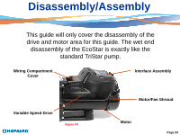
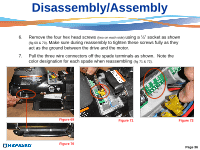
Disassembly/Assembly 6. Remove the four hex head screws (two on each side) using a ¼" socket as shown (fig 69 & 70). Make sure during reassembly to tighten these screws fully as they act as the ground between the drive and the motor. 7. Pull the three wire connectors off the spade terminals as shown. Note the color designation for each spade when reassembling (fig 71 & 72). Figure 69 Figure 70 Figure 71 Figure 72 Page 36
-
 1
1 -
2
-
3
-
4
-
5
-
6
-
7
-
8
-
9
-
10
-
11
-
12
-
13
-
14
-
15
-
16
-
17
-
18
-
19
-
20
-
21
-
22
-
23
-
24
-
25
-
26
-
27
-
28
-
29
-
30
-
31
-
32
-
 33
33 -
 34
34 -
 35
35 -
 36
36 -
 37
37 -
 38
38 -
 39
39 -
 40
40 -
 41
41 -
 42
42 -
 43
43 -
44
-
45
-
46
-
47
-
48
-
49
-
50
 |
 |

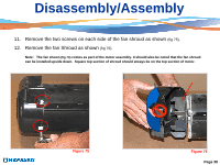
6.
Remove the four hex head screws
(two on each side)
using a ¼” socket as shown
(fig 69 & 70).
Make sure during reassembly to tighten these screws fully as they
act as the ground between the drive and the motor.
7.
Pull the three wire connectors off the spade terminals as shown.
Note the
color designation for each spade when reassembling
(fig 71 & 72).
Disassembly/Assembly
Figure 72
Figure 71
Figure 69
Figure 70
Page 36