Hayward HP21404TC HeatPro_Square_Manual_Rev_G_5148 - Page 14
Pad Plumbing Layou, NOTICE, UNIONS, Included Union Connectors, INSTALLATION ABOVE
 |
View all Hayward HP21404TC manuals
Add to My Manuals
Save this manual to your list of manuals |
Page 14 highlights
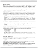
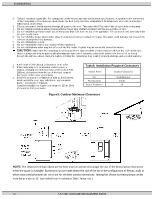
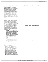
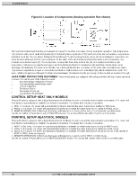
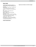
51300003301G Figure5: Pad Plumbing Layout CAUTION: Improperly adjusted manual bypass valves will result in damage to the heater if the flow rates are not maintained under all operating conditions as specified in listed SPECIFICATION. The heat exchanger will fail and this damage will not be covered under the manufacturer's warranty. CAUTION: The heat pump must be protected from back siphoning of water. If there is any chance of back siphoning, provide a check valve between the pool and the filter pump inlet. Failure to follow the instructions may result in property damage due to flooding. CAUTION: Automatic erosion type chlorinators, if used, must be installed downstream (between the heat pump and the pool) of the heat pump, and a check valve (or Hartford Loop) installed in a manner that will not allow the raw chlorine to drain back to the heat pump when the water pump is off. Failure to follow the instructions may result in property damage. CAUTION: Do not pour chemicals directly into the skimmer. It could result in damage to your system and heat pump. Arrangement of pool system components other than as illustrated in figure5 can affect the operation of the heat pump's water pressure switch. Location of the heat pump above or below the elevation of the pool water surface can also affect operation of the switch. In general, the pressure switch can be adjusted to accommodate this effect if the heat pump water connections are no more than six (6) feet [1,8 m] below the pool water surface or no more than fifteen (15) feet [4,6 m] above it. See instructions for pressure switch adjustment in the START-UP section of this manual. If the heat pump is installed outside of this range, an external pressure switch may need to be installed in the plumbing upstream of the heat pump. NOTICE: Be advised, that when pool equipment is located below the pool surface, a leak at this lower level can result in large-scale water loss or flooding. Manufacturer is not responsible for water loss or damage it causes . UNIONS: The heater is equipped with two Figure6: Included Union Connectors detachable union connectors, (2 union nuts and 2 gaskets) included with the heat pump. These fittings must be installed on the heat pump water inlet and outlet to facilitate servicing and winterizing the unit. (See figure6). Heat sinks, heat tapes, firemen switches, and check valves are not required on the heater. However, if there is any chance of "back-siphoning" of hot water when the pump stops running, it is suggested that a check valve be used on the heater outlet pipe down stream of bypass system INSTALLATION ABOVE POOL/SPA SURFACE: If 14 USE ONLY GENUINE REPLACEMENT PARTS
-
 1
1 -
2
-
3
-
4
-
5
-
6
-
7
-
8
-
 9
9 -
 10
10 -
 11
11 -
 12
12 -
 13
13 -
 14
14 -
 15
15 -
 16
16 -
 17
17 -
 18
18 -
 19
19 -
20
-
21
-
22
-
23
-
24
-
25
-
26
-
27
-
28
-
29
-
30
-
31
 |
 |
