Hayward HP21404TC HeatPro_Square_Manual_Rev_G_5148 - Page 26
Troubleshooting
 |
View all Hayward HP21404TC manuals
Add to My Manuals
Save this manual to your list of manuals |
Page 26 highlights
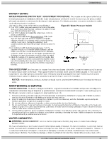
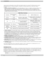
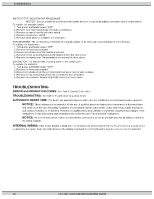
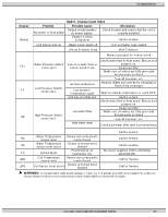
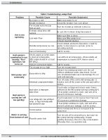
51300003301G SWITCH TEST / ADJUSTMENT PROCEDURE. NOTICE: Do not operate the pool heater without the function of a properly adjusted pressure switch or flow switch. To replace the pressure switch: 1. Turn pump, and heater power "OFF". 2. Remove hose from switch body external to control box. 3. Remove the wires from the pressure switch. 4. Replace the pressure switch. 5. Reverse steps above to complete the procedure. TRANSFORMER: The transformer converts the field supply voltage to 24 VAC output for powering the control board. To replace the transformer: 1. Turn pump, and heater power "OFF". 2. Remove the front access panel. 3. Disconnect all wires from the transformer leads. 4. Remove the (2) screws that secure the transformer to the control box. 5. Replace the transformer. Reassembly is the reversal of steps above. CONTACTOR: The switches the incoming power to the compressor. To replace the contactor: 1. Turn pump, and heater power "OFF". 2. Remove the front access panel. 3. Disconnect all wires from the contactor terminals keep track of wire locations. 4. Remove the (2) screws that secure the contactor to the control box. 5. Replace the contactor. Reassembly is the reversal of steps above. TROUBLESHOOTING ERROR and OPERATION CODES: See Table 5: Display Code Index. TROUBLESHOOTING: See Table 6: Troubleshooting Lookup Chart. AUTOMATIC RESET TIME: The heater will automatically reset when an error condition is corrected and resume operation. NOTICE: These instructions are intended for the use of qualified personnel trained and experienced in the installation and servicing of this type of heating equipment and its related system components. Some states may require installation and service personnel to be licensed. Persons not qualified should not attempt to repair this equipment according to these instructions. These instructions and procedures are not for the use of "do-it-yourself" consumers. NOTICE: As a preliminary check, make sure that all wire connections are clean and tight and that all wiring conforms to the wiring diagram. INTERNAL WIRING: If the heater display is blank after the electrical has been installed, refer to Troubleshooting Lookup Chart to determine the cause. Note, the cable between the display board and the terminal board is keyed to ensure correct connection. 26 USE ONLY GENUINE REPLACEMENT PARTS
-
 1
1 -
2
-
3
-
4
-
5
-
6
-
7
-
8
-
9
-
10
-
11
-
12
-
13
-
14
-
15
-
16
-
17
-
18
-
19
-
20
-
 21
21 -
 22
22 -
 23
23 -
 24
24 -
 25
25 -
 26
26 -
 27
27 -
 28
28 -
 29
29 -
 30
30 -
 31
31
 |
 |
