Hayward HP21404TC HeatPro_Square_Manual_Rev_G_5148 - Page 15
TYPICAL POOL ARRANGEMENT, NOTICE, Heater Installation Above Pool, Typical Plumbing
 |
View all Hayward HP21404TC manuals
Add to My Manuals
Save this manual to your list of manuals |
Page 15 highlights
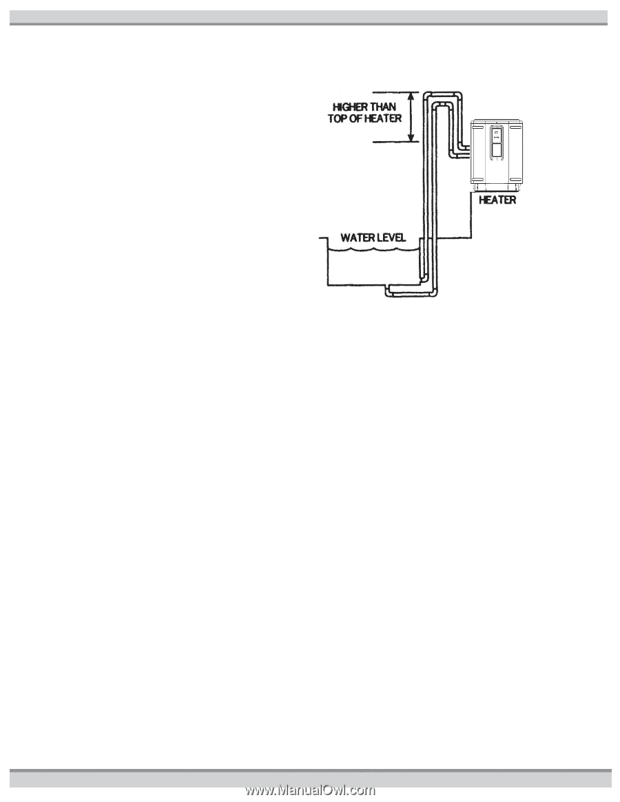
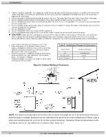
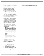
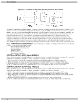
the heater is installed less than three (3) feet above the surface of the pool/spa water, install eyeball fittings or directional flow fittings on the end of the return water line to the pool/spa to create adequate back pressure at the heater to operate the pressure safety switch when the pump is running. If the heater is installed more than three (3) feet above the surface of the pool/spa water, install a loop as shown in Figure7 to prevent drainage of water in the heater during a filter change. For installation above or below the pool/spa surface, refer to START UP section for proper pressure switch setup. TYPICAL POOL ARRANGEMENT: Figure8 illustrates a typical pool piping diagram and layout for the pool equipment. Also shown is implementation of an optional Gas or Solar heater system for additional capacity. Other pool heaters, such as gasfired or solar-powered devices must be installed in a parallel circuit and operated independently (only one at a time) for your warranty to be valid. NOTICE - Because of the intense heat that can be generated by gas and solar units, isolating it with a shut-off valve and a check valve when gas or solar heater is in operation protects the heat pump. Failure to follow the instructions may result in property damage. Notes: 1. Isolate the heat pump from hot water flow of heating devices such as gas or solar heater. 2. Install bypass loop for heat pump unit. Figure9 illustrates a multiple heater installation for very large pools with and without a manual bypass valve. 1. Maintain 4-6ft [1,2-1,8 m] clearance between the units, 2ft [0,6 m] around perimeter, and at least 6ft [1,8 m] over them. Refer to LOCATING THE HEATER section for more details. 2. Install bypass loops for each unit. 3. Install union style fittings from the heat pump CONSUMER KIT adjacent to the unit to facilitate easy service procedures 51300003301G Figure7: Heater Installation Above Pool Figure8: Typical Plumbing to Pool Figure9: Multiple Heater System USE ONLY GENUINE REPLACEMENT PARTS 15
-
 1
1 -
2
-
3
-
4
-
5
-
6
-
7
-
8
-
9
-
 10
10 -
 11
11 -
 12
12 -
 13
13 -
 14
14 -
 15
15 -
 16
16 -
 17
17 -
 18
18 -
 19
19 -
 20
20 -
21
-
22
-
23
-
24
-
25
-
26
-
27
-
28
-
29
-
30
-
31
 |
 |