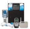
Hayward Pro Logic Model: PL-P-4 Installation
Hayward Pro Logic Manual
 |
View all Hayward Pro Logic manuals
Add to My Manuals
Save this manual to your list of manuals |
Hayward Pro Logic manual content summary:
- Hayward Pro Logic | Model: PL-P-4 Installation - Page 1
menu day and time water temperature air temperature chlorinator setting salt level reason pump is running (not scheduled) inspect cell reason hi-speed is running (not scheduled) countdown time remaining heater control status system manual off check system error filter vsp speed/reason lights/aux - Hayward Pro Logic | Model: PL-P-4 Installation - Page 2
INSTRUCTIONS LIMITED WARRANTY (effective 04/01/09) Hayward/Goldline warrants its Pro Logic and E-Command pool automation products as well as its Aqua Rite, Aqua Rite Pro, Aqua Plus and SwimPure chlorination products to be free of defects in materials and workmanship, under normal use and service - Hayward Pro Logic | Model: PL-P-4 Installation - Page 3
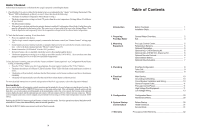
Pool/Spa Configuration 8 Turbo Cell 9 Flow Switch 9 Main Service 10 Grounding and Bonding 10 Circuit Breaker Installation and Wiring 10 General Purpose Outlet 11 Pro Logic Control Power 11 High Voltage Pool Equipment 11 Low Voltage Wiring 13 Configuration Menu 20 Maintenance Menu 30 - Hayward Pro Logic | Model: PL-P-4 Installation - Page 4
2. Pool/spa salt level is between 2700 - 3400 PPM. 3. Properly rated circuit breakers are installed in the Pro Logic subpanel. 4. All wiring is performed according to NEC and local codes. 5. The Pro Logic is properly grounded and bonded. 6. The Pro Logic is properly configured to control all desired - Hayward Pro Logic | Model: PL-P-4 Installation - Page 5
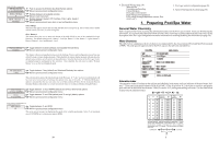
/next configuration menu This is the unit of measure for displaying the speed of the variable speed pump. Select % of maximum speed (3450 RPM) or revolutions per minute (RPM). 29 4. Electrical Wiring (page 10) Main service Grounding and bonding Circuit breakers Pro Logic control power High - Hayward Pro Logic | Model: PL-P-4 Installation - Page 6
the selected freeze temperature threshold, the Pro Logic will turn on the valve to allow circulation of the water. IMPORTANT: this only enables operation of the valve3 output during freeze--see the "Filter Pump Config." menu to enable freeze protection for the main circulation system. Valve3 Pump - Hayward Pro Logic | Model: PL-P-4 Installation - Page 7
protection temperature, the Pro Logic will turn on the aux relay to circulate the water. IMPORTANT: this only enables operation of the AUX output during freeze--see the "Filter Pump Config." menu to enable freeze protection for the main circulation system. Freeze Protection is not available for low - Hayward Pro Logic | Model: PL-P-4 Installation - Page 8
falls below the selected freeze temperature threshold, the Pro Logic will energize the lights relay. IMPORTANT: this only enables operation of the lights relay during freeze--see the "Filter Pump Config." menu to enable freeze protection for the main circulation system. Lights Pump Speed This is - Hayward Pro Logic | Model: PL-P-4 Installation - Page 9
page 17) for instructions on running the cable from the Pro Logic main unit to the remote display/keypad. AQL-SS-6B-x (x=W or B for White or Black) The AQL-SS-6B is a double insulated, waterproof device which is intended for installation at the water's edge. The remote control comes with an attached - Hayward Pro Logic | Model: PL-P-4 Installation - Page 10
on the Pro Logic main control unit is 400 feet (120m) line of sight or 200 feet (60m) through walls, etc. If in doubt about the distance, test operation before installing the remote. All wireless models require the user to run the "Teach Wireless" routine in the Settings Menu. This information - Hayward Pro Logic | Model: PL-P-4 Installation - Page 11
system is in the "pool only" operating mode. 6. The plumbing diagram above is intended to be used as a general guideline and is not a complete plumbing schematic for the pool. 7. The air sensor must be installed if the freeze protection feature is enabled for the filter, valves or aux outputs - Hayward Pro Logic | Model: PL-P-4 Installation - Page 12
is configured, one of the AUX relays must also be configured to control the low speed motor winding on the pump. Refer to the appropriate sections in the Installation manual for specific information regarding the control logic for 2-speed and variable speed pump operation. For the Hayward variable - Hayward Pro Logic | Model: PL-P-4 Installation - Page 13
x x AQL-CHEM Connector "Local" Display Flow Switch Cell Connector Subpanel High Voltage Relays Control Power Input pH Dispense Output Ground Bus Bar Bonding Lug(s) The Pro Logic Control Center requires both high and low voltage connections. Low voltage connections will be made to actuators - Hayward Pro Logic | Model: PL-P-4 Installation - Page 14
Pro Logic will automatically detect and control any Aqua Rite(s) installed in the system. Display Allows for the display of salt (default) or mineral values. Cell Type Selection The Cell Type Menu appears after "Display Salt/Minerals" in the Chlorinator Configuration Menu. The options are T-CELL - Hayward Pro Logic | Model: PL-P-4 Installation - Page 15
the "Lights" relay and then connect the color wheel to one of the AUX outputs. Hayward Variable Speed Pump: Proper installation of a Hayward Variable Speed Pump (VSP) includes high voltage input wiring, low voltage communication wiring, and menu configuration/settings. The Pro Logic can control up - Hayward Pro Logic | Model: PL-P-4 Installation - Page 16
heaters, contact Hayward Tech support, 908-355-7995. Refer to the diagrams and the information on the following pages for more details on the connection to several popular heaters. Generic Heaters 1. Wire heater to 120/240V power source per the instructions in the heater manual. The Pro Logic - Hayward Pro Logic | Model: PL-P-4 Installation - Page 17
white remove jumper white Fusible Link Hayward Heaters Refer to the instructions in the heater manual for "2-wire Remote Thermostat" operation under "Remote Control Connections" and the diagram below: 1. Turn off power to heater. 2. Wire Pro Logic to terminals 1 & 2 (see diagram). 3. Leave - Hayward Pro Logic | Model: PL-P-4 Installation - Page 18
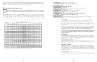
Refer to your TriStar or EcoStar manual(s) for proper low voltage communication wiring between the Pro Logic and the Hayward Variable Speed Pump. A pump address must be configured for each VSP used in the system. This address is entered into the VSP's configuration menu. Refer to the table below to
-
 1
1 -
 2
2 -
 3
3 -
 4
4 -
 5
5 -
 6
6 -
 7
7 -
8
-
9
-
10
-
11
-
12
-
13
-
14
-
15
-
16
-
17
-
18
 |
 |

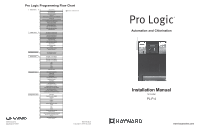
Pro Logic Programming Flow Chart
092337C RevF
Copyright © 2010 Hayward
Automation and Chlorination
Installation Manual
for model
PL-P-4
Pro Logic
®
620 Division St.
Elizabeth, NJ
07207
www.haywardnet.com
denotes conditional items
default menu
day and time
water temperature
air temperature
chlorinator setting
salt level
reason pump is running (not scheduled)
inspect cell
reason hi-speed is running (not scheduled)
countdown time remaining
heater control status
system manual off
check system error
filter vsp speed/reason
lights/aux speed/reason
pH/ORP levels
settings menu
spa heater1 temperature
pool heater1 temperature
spa solar temperature
pool solar temperature
vsp speed settings
superchlorinate
spa chlorinator setting
pool chlorinator setting
day and time
backlit display light
beeper
teach wireless remote
wireless channel
maintenance menu
pH calibration wizard
clean probe wizard
timers menu
pool filter 1 or hi-speed 1
pool filter 2 or lo-speed 1
pool filter 3 or hi-speed 2
pool filter 4 or lo-speed 2
spa
lights
aux1
aux2
valve3
superchlorinate
diagnostic menu
chlorinator diagnostics
instant salt
pH/orp levels
flow switch
cell temperature sensor
water/pool sensor
air sensor
solar sensor
vsp speed/power
main software revision
display software revision
chemistry sense module software
vsp software revision
RF base software revision
6 button spa side software revision
configuration menu
chlorinator
chemistry config. Wizard
pool/spa
filter
heater1
solar
external input active state
lights
aux1
aux2
valve3
6 button spa side remote
remote menus
7-day or weekend/weekday timeclock
12 hour or 24 hour time format
ºF or ºC
vsp speed (% or rpm)
reset to default