Hayward Pro Logic Model: PL-P-4 Installation - Page 13
Electrical Wiring - pool panel
 |
View all Hayward Pro Logic manuals
Add to My Manuals
Save this manual to your list of manuals |
Page 13 highlights
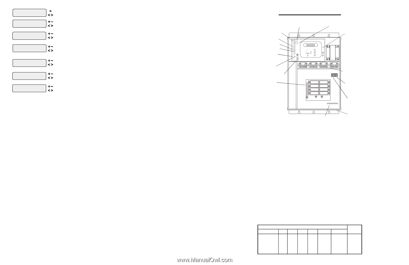
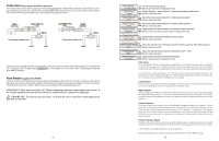
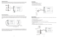
Pool/Spa Config. + to view/change Push to access Pool/Spa options Move to previous/next configuration menu Pool/Spa Setup Pool and Spa if "Pool and Spa" is selected Spa - CountDn 00:30 Rotates between Pool Only (default), Spa Only and Pool and Spa Move to next menu item Adjust time setting (Manual On/Off, 0:05, 0:10, 0:15..., (default is 4:00)) Move to next menu item if "Pool and Spa" is selected Spa Spillover Toggle between Enabled and Disabled (default) Spa Spillover Enabled Move to next menu item or previous/next configuration menu if "Pool and Spa" is selected and if "Spa Spillover" is enabled Filter Operation Spa Spillover Toggle between Pool Only (default) and Spa Spillover options Move to previous/next configuration menu if "Pool Only" or "Spa Only" is selected V1=Aux1, V2=Aux2 Toggle between Enabled and Disabled (default) Disabled Move to previous/next configuration menu if "Pool and Spa" is selected Filter Off Valve Change: Enabled Toggle between Enabled (default) and Disabled Move to previous/next configuration menu Pool/Spa Setup If "Pool Only" or "Spa Only" are selected, then the pool/spa valves are not needed and pushing the POOL/ SPA button on the display/keypad will have no effect. If "Pool and Spa" is selected, then the pool/spa suction and return valve actuators should be connected to the Pro Logic. Pressing the POOL/SPA button on the display/keypad will allow the homeowner to alternate between pool and spa operation. Spa CountDn This menu will appear only if Pool/Spa Setup is set to "Pool and Spa". This setting is the time, after you manually switch the Pool/Spa valves to "Spa Only", until the Pro Logic automatically returns the valves to their previous positions. It is programmed in increments of 5 minutes, from "Manual On/Off" (0 minutes) to "21:00" (21 hours). The filter is forced on during this time period. Spa Spillover When spa spillover is "Enabled" and "Pool and Spa", the homeowner will be able to rotate through "Pool Only" (both suction and return valves switched to pool), "Spa Only" (both suction and return valves switched to spa) and "Spillover" (suction valve switched to pool and return valve switched to spa) by successive presses of the "Pool/Spa button. Filter Operation If "Spa Spillover" is selected, the Pro Logic will automatically switch the pool/spa suction and return valves to "spillover" at the start of the programmed pool filtering time period or when the super-chlorinate function is turned on. The valves will remain in this position for the remainder of the super-chlorinate period. This option is usually preferable because both the pool and spa water will be filtered and sanitized. If "Pool Only" is selected, then the Pro Logic will switch the pool/spa valves to the "pool only" position at the start of the programmed pool filtering time period or when the super-chlorinate function is turned on. This may be desirable on some systems with in-floor cleaners because it allows the cleaner to operate all the time the pool is being filtered and/or the super chlorinate is running. V1=Aux1, V2=Aux2 This menu appears only if the Pool/Spa Setup is "Pool Only" or "Spa Only". When enabled, Valve 1 (return) will follow the Aux1 output and Valve 2 (suction) will follow the Aux2 output. When disabled (default), the return and suction pool/spa valves function normally. Filter Off Valve Change This menu appears only if Pool/Spa setup is set to "Pool and Spa - Std". When enabled (default), the filter pump will shut off for 35 seconds whenever the Pool/Spa valves are turning. The pump will NOT shut off when a heater is in Heater Cooldown mode. 21 4. Electrical Wiring Remote Keypad Wireless Base Receiver Connector Temp Sensor Inputs External Input Heater Output Valve Connectors x x AQL-CHEM Connector "Local" Display Flow Switch Cell Connector Subpanel High Voltage Relays Control Power Input pH Dispense Output Ground Bus Bar Bonding Lug(s) The Pro Logic Control Center requires both high and low voltage connections. Low voltage connections will be made to actuators, sensors, remote keypad, etc. High voltage connections will be made to pumps, lights, etc., as well as providing direct input power to the Control Center. Always: -Ensure that Power is disconnected prior to doing any wiring -Follow all local and NEC (CEC if applicable) codes -Use copper conductors only Main Service (Power to the Circuit Breaker Subpanel) The Pro Logic circuit breaker subpanel is rated for 100A service. Run properly rated conductors (L1, L2, N, and ground) from the primary house electrical panel to the main power connections on the Pro Logic circuit breaker base. The connection at the main house panel should be to a 240VAC circuit breaker rated at 100A maximum. Grounding and Bonding Connect a ground wire from the primary electrical panel to the Pro Logic ground bus bar. Also ground each piece of high voltage (120 or 240VAC) equipment that is connected to the Pro Logic control relays or circuit breakers. The Pro Logic should also be connected to the pool bonding system by an 8AWG (6AWG for Canada) wire. A lug for bonding (2 for Canada) is provided on the outside/bottom of the Pro Logic enclosure. Circuit Breaker Installation and Wiring Circuit breakers are to be supplied by the installer. Refer to the circuit breaker chart below for a list of suitable circuit breakers that can be used. Follow the code and the circuit breaker manufacturer's rating requirements regarding the size and temperature rating for wiring. Note that some pool equipment may be required to be connected to ground fault circuit breakers-check local and NEC (CEC) codes. Manufacturer SUITABLE LISTED BREAKERS Single Double Twin Quad GFCB Tightening Filler Plates Torque Cutler-Hammer BR Murray MP-T Siemens QP Square D HO M Thomas & Betts TB G.E. THQL BR MP-T QP HOM TB THQL BRD MH-T QT HOMT TBBD BRD MH-T QT HOMT TBBQ GFCB MP-GT QPF HOM-GFI GFB THQL-GF BRFP LX100FP QF3 HOMFP FP-1C-TB TFH 25lb-in 25lb-in 25lb-in 25lb-in 25lb-in 25lb-in 10
-
 1
1 -
2
-
3
-
4
-
5
-
6
-
7
-
 8
8 -
 9
9 -
 10
10 -
 11
11 -
 12
12 -
 13
13 -
 14
14 -
 15
15 -
 16
16 -
 17
17 -
 18
18
 |
 |