Hayward Pro Logic Model: PL-P-4 Installation - Page 9
Optional AQL-CHEM2 CO, Dispensing Kit, Optional Remote Controls - pool lights
 |
View all Hayward Pro Logic manuals
Add to My Manuals
Save this manual to your list of manuals |
Page 9 highlights
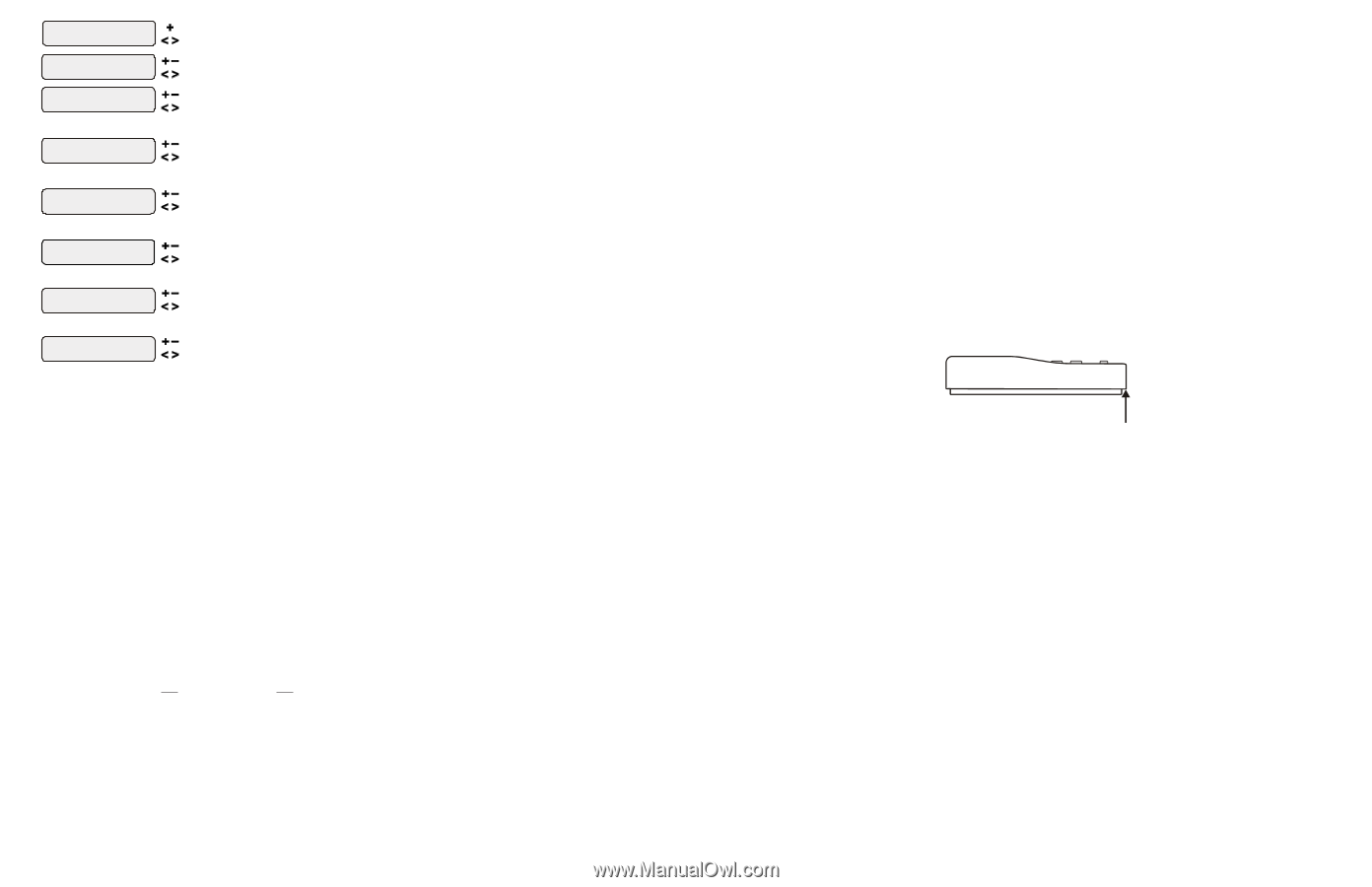
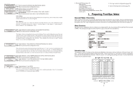
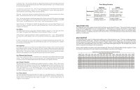
Lights Config. + to view/change Push to access Lights options Move to previous/next configuration menu Lights Name Pool Light Rotates between all available names Move to next menu item or previous/next configuration menu Lights Function Manual On/Off for manual on/off, countdown timer and timeclock functions Lights Relay Standard Rotates between Manual On/Off (default), Countdown Timer, Low Speed- Filter, Timeclock, Solar, and Super Chlorinate Move to next menu item Toggle between Standard (default), Dimmer and VSP Move to next menu item or previous/next configuration menu for all functions except solar, dimmer relay, super chlorinate and low speed Lights Interlock Toggle between Enabled and Disabled (default) Lights Interlock Disable Move to next menu item for all functions except solar, dimmer relay, super chlorinate pH dispense, low speed, and group Lights Ext Input Toggle between Enabled and Disabled (default) Disabled Move to previous/next configuration menu for all functions except dimmer relay, super chlorinate pH dispense, low speed, and group Lights Freeze Toggle between Enabled and Disabled (default) Lights Freeze Disable Move to previous/next configuration menu if filter pump is set to variable speed and the relay type is set to standard Lights Pump Spd Select Settings Menu (default) or desired pump speed (Filter Lowest to Highest) Settings Menu Move to previous/next configuration menu Lights Function Although designated as the "Lights" output, the function of the lights relay is similar to the aux1 and aux2 relays. If pool lights are wired to the lights relay, some options including Solar function, Low Speed of a 2Speed Filter Pump, Lights Interlock and Lights Freeze Protection will not be necessary and should be disabled. If no pool lights are used, the lights relay can be used to control other pool devices that may require these options. The function of each option is shown below. Manual On/Off (default)-the lights relay will alternate between turning on and off when the LIGHTS button is pressed. There is no automatic control logic. Countdown Timer-the lights relay will turn on when the LIGHTS button is pressed. The lights relay will turn off automatically after a programmed time (see Timers Menu in Operation Manual). The LIGHTS button can also be used to turn the output off. Low Speed of a 2-speed Filter Pump - the Pro Logic will turn on the lights relay whenever the low speed operation of the filter pump is required. It is very important that the "2-speed" filter pump option be selected under the "Filter Config." Menu for proper operation. Timeclock - the lights relay will turn-on and turn-off at the times set for the lights timeclock in the Timers Menu (see Timers Menu in Operation Manual). The LIGHTS button can also be used to turn the output on and off. Solar - the lights relay can operate a solar booster pump which will turn on when the filter pump is running and solar heat is available and the water is less than the desired temperature setting. It is important to note that "Solar Control" must be enabled in the "Solar Config." menu for proper operation to occur. Super Chlorinate - if "Chlorinator" is enabled, this option allows the user to start a Super Chlorinate cycle when the Lights button is pressed, rather than using the Settings Menu. Note that only one button can be assigned to this function. Lights Relay This feature allows the user to select either "Standard" (default), "Dimmer" or "VSP" type relay for the Lights output. The optional AQL-DIM dimmer kit must be installed if "Dimmer" is desired. When "Dimmer" is selected, and the Lights output is manually turned on, the "+" and "-" buttons adjust the level from 20% to 100% (default). The level is saved for the next time the lights are turned on. 25 OTChHpeEAtMiQo,Ltnh-eaCPlHrAoELMQo2gLiics-Cwa CiHllOsE2endMsise2ptehCnespOionog2ld'DsepviHiscpleetveheanltascnoidnnanugetcoKtms diattiirceacltllyydtiosptheensPertohLe ocogrirce.cWt amheonuunsteodf the pool's pH to the desired level. Wiring and plumbing requirements for the AQL-CHEM2 should with an AQLCbeOc2otonsciodnetrreodl before installing the Pro Logic. Refer to the AQL-CHEM2 manual for specific installation information. Optional Remote Controls Hayward offers a variety of wired and wireless remote control options for the Pro Logic. Each model gives you the ability to control your pool's functions from a remote location, away from the Control Center. Wired Remote Controls Up to 3 wired remote controls can be installed. See page 17 for wiring information. AQL-WW-P-4 The AQL-WW-P-4 display/keypad must be mounted indoors or in a weather protected area (rain should never touch the unit). The display/keypad is designed to mount onto a standard electrical utility box (same box as a single light switch, ideal for new construction) or can be mounted directly onto any wall surface. When selecting a location, note that the wire to the Pro Logic main unit must be less than 500' long. Refer to the remote's installation instructions as well as the steps below: 1. Remove display/keypad baseplate from the cover by lifting up on the cover at the lower end of the keypad. See diagram below. Remote Keypad push up here to remove cover 2. Screw the baseplate in the desired position (screws supplied by installer). 3. See "Electrical Wiring" (page 17) for instructions on running the cable from the Pro Logic main unit to the remote display/keypad. AQL-SS-6B-x (x=W or B for White or Black) The AQL-SS-6B is a double insulated, waterproof device which is intended for installation at the water's edge. The remote control comes with an attached 150' cable and is typically installed at the tile-line of the spa wall, or in the deck, within arm's reach of a pool/spa occupant. Refer to the AQL-SS-6B installation manual for specific mounting and wiring information. 6
-
 1
1 -
2
-
3
-
 4
4 -
 5
5 -
 6
6 -
 7
7 -
 8
8 -
 9
9 -
 10
10 -
 11
11 -
 12
12 -
 13
13 -
 14
14 -
15
-
16
-
17
-
18
 |
 |