Hayward Pro Logic Model: PL-P-4 Installation - Page 8
Mounting the Equipment - pl p 4
 |
View all Hayward Pro Logic manuals
Add to My Manuals
Save this manual to your list of manuals |
Page 8 highlights
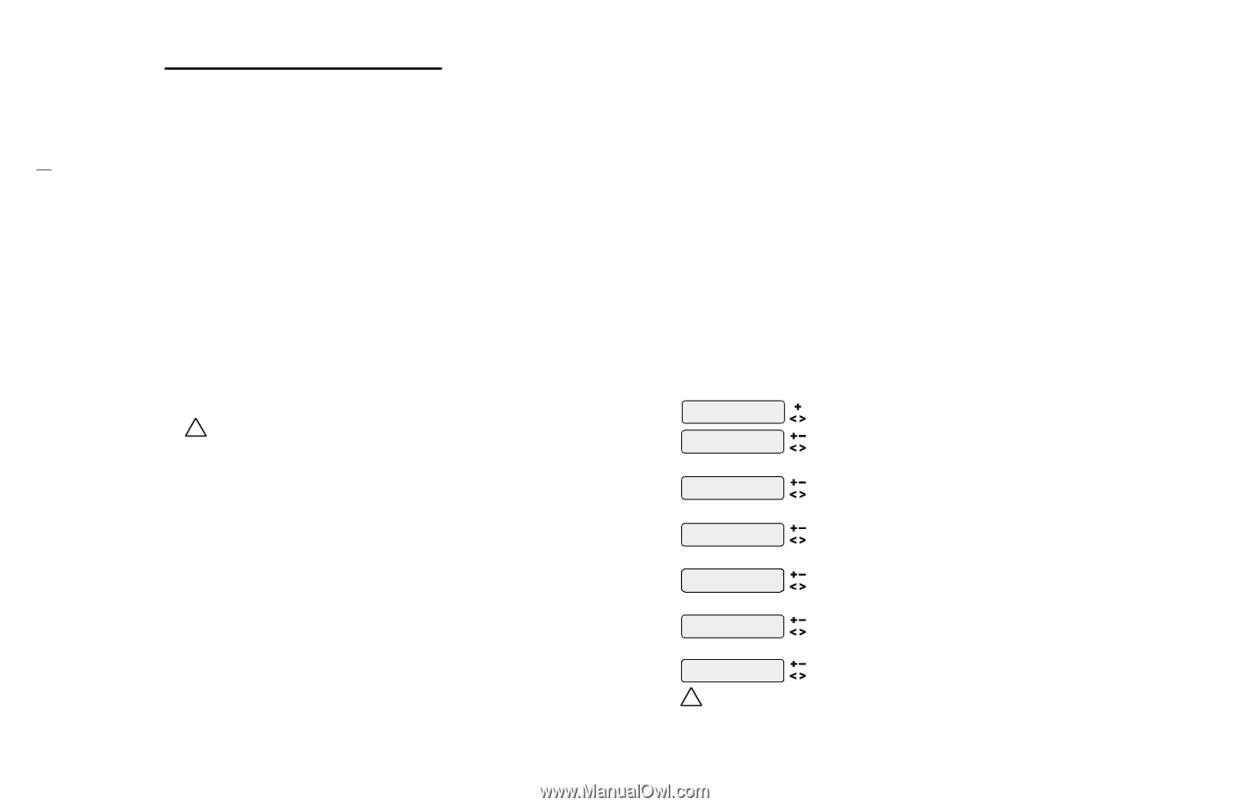
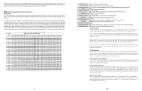
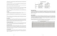
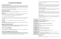
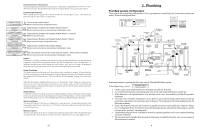
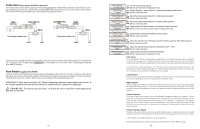
2. Mounting the Equipment Pro Logic Control Center The Pro Logic is contained in a raintight enclosure that is suitable for outdoor mounting. The control must be mounted a minimum of 5 ft. (2 meters) horizontal distance from the pool/spa (or more, if local codes require). The Control Center is designed to mount vertically on a flat surface with the knockouts facing downward. Because the enclosure also acts as a heat sink (disperses heat from inside the box), it is important not to block the four sides of the control. Do not mount the Pro Logic inside a panel or tightly enclosed area. When selecting a location, note that the standard cables supplied with the Turbo Cell, flow switch, temperature sensors, and valve actuators (if applicable) are all 15 ft. (5m) long. Temperature Sensors Three sensors are included with the Pro Logic. A water sensor and an air sensor must be installed at all times for proper operation. A solar sensor is required if the solar function is enabled. Water Sensor This sensor is used to measure the pool/spa temperature and is installed in the filtration plumbing after the filter but before either the solar or conventionally fueled heaters-refer to the plumbing overview diagram. 1. Drill a 3/8" (10mm) diameter hole in the PVC piping and remove all chips and burrs. 2. Insert sensor until O-ring collar sits flush on the hole. 3. Position hose clamp over the sensor and gently tighten until O-ring makes an adequate seal. Do not overtighten. 4. For maximum temperature accuracy, cover the sensor and 3" (6cm) of pipe on either side with insulation and white paint. Air Sensor Mount the air sensor outdoors. ! IMPORTANT: Mount the air sensor out of direct sunlight. Solar Sensor For solar applications, mount the sensor near the solar collector array so that it is exposed to the same sunlight as the collectors. Use additional cable (20 AWG) if necessary. Optional Chlorination Function The PL-P-4 model requires the use of a chlorinator cell and plumbing kit to provide pool chlorination. These items are not included with the Pro Logic and can be purchased separately at your local Hayward dealer. Choose a chlorinator cell model based on the size of your pool. The following models are available: T-CELL-15 for pools up to 40,000 gallons T-CELL-9 for pools up to 25,000 gallons T-CELL-3 for pools up to 15,000 gallons In addition to the chlorinator cell, a plumbing kit (P-KIT) must be purchased. This kit contains the cell unions and flow switch. Refer to pages 8 and 18 for plumbing and wiring instructions. Optional AQL-CHEM ORP and pH Sensing Kit The AQL-CHEM is an ORP and pH sensing kit for the Pro Logic. When chlorination is enabled (requires chlorinator cell and P-KIT), the Pro Logic senses the pool's ORP and pH levels and generates the correct amount of chlorine to keep your pool properly sanitized. Wiring and plumbing requirements for the AQL-CHEM should be considered before installing the Pro Logic. Refer to the AQL-CHEM manual for specific installation information. 5 If "VSP" is selected, the Lights relay is used to supply power to a Hayward Variable Speed Pump (VSP). The relay will be on when the Lights output is on and off when the output is off . On, off and speed are controlled by commands sent to the VSP. Lights Interlock If enabled, this feature will override the function (Manual On/Off, Countdown Timer, Timeclock) selected above and turn the lights relay off when: filter pump is off, first 3 minutes of filter pump operation (allows the pump to prime and get water flowing), when the pool/spa suction return valves are in any position other than "pool only", or for the first 3 minutes after solar turns on (allows air in the solar panels to be purged). Interlock is not available for solar, low speed filter pump, super chlorinate or dimmer. Lights External Input Interlock When Lights External Input Interlock is enabled, the lights output will be forced off when the external input is active. This will have precedence over freeze protection. Lights External Input Interlock is not available for solar, low speed filter pump, dimmer, super chlorinate, or pH dispense functions. Lights Freeze Protection This function helps protect equipment that is wired to the lights relay against freeze damage. If Freeze Protection is enabled and the AIR temperature sensor falls below the selected freeze temperature threshold, the Pro Logic will energize the lights relay. IMPORTANT: this only enables operation of the lights relay during freeze--see the "Filter Pump Config." menu to enable freeze protection for the main circulation system. Lights Pump Speed This is the speed of the filter pump when the Lights output is on. The default selection is "Settings Menu". This is the speed of the pump that has been selected in the Settings Menu for normal filter operation. If an alternate speed is desired when the Lights output is on, push "+" or "-" and select from "Filter Lowest" to "Filter Highest" in 5% increments. NOTE: The configuration parameters for the Aux2 output are the same as shown below for Aux1. Aux1 Config. + to view/change Push to access Aux options Move to previous/next configuration menu Aux1 Function Manual On/Off for manual on/off, countdown timer and timeclock functions Aux1 Relay Standard Rotates between Manual On/Off (default), Countdown Timer, Low Speed- Filter, Timeclock, Solar, and Super Chlorinate Move to next menu item Toggle between Standard (default), Dimmer and VSP Move to next menu item or previous/next configuration menu for all functions except solar, dimmer relay, super chlorinate and low speed Aux1 Interlock Toggle between Enabled and Disabled (default) Aux1 Interlock Disable Move to next menu item for all functions except solar, dimmer relay, super chlorinate and low speed Aux1 Ext Input Toggle between Enabled and Disabled (default) Disabled Move to previous/next configuration menu for all functions except dimmer relay, super chlorinate and low speed Aux1 Freeze Toggle between Enabled (default) and Disabled Aux1 Freeze Disable Move to previous/next configuration menu if filter pump is set to variable speed and the relay type is set to standard Aux1 Pump Spd Select Settings Menu (default) or desired pump speed (Filter Lowest to Highest) Settings Menu Move to previous/next configuration menu ! WARNING: Do not use the Pro Logic to control an automatic pool cover. Swimmers may become entrapped underneath the cover. Aux1 Function Manual On/Off (default)-the aux relay will alternate between turning on and off when the aux button is pressed. There is no automatic control logic. 26
-
 1
1 -
2
-
 3
3 -
 4
4 -
 5
5 -
 6
6 -
 7
7 -
 8
8 -
 9
9 -
 10
10 -
 11
11 -
 12
12 -
 13
13 -
14
-
15
-
16
-
17
-
18
 |
 |