Hayward Pro Logic Model: PL-P-4 Installation - Page 17
Laars Heaters, Hayward Heaters, Temperature Sensors, Remote Display/Keypad - circuit board
 |
View all Hayward Pro Logic manuals
Add to My Manuals
Save this manual to your list of manuals |
Page 17 highlights
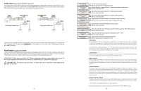
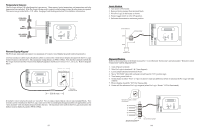
Temperature Sensors The Pro Logic utilizes 10K ohm thermistor type sensors. Three sensors (water temperature, air temperature and solar temperature) are included. If the Pro Logic is being used to control a solar heating system, the solar sensor is required. The sensors are provided with a 15 ft. cable. See page 5 and the diagram below for installation information. POOL/SPA SENSOR AIR SENSOR SOLAR/SPA SENSOR Remote Display/Keypad The Pro Logic main unit can connect to a maximum of 3 remote wired display/keypads (ordered separately). Use four conductor cable (typically phone cable) to connect the wired remote display/keypad with the Pro Logic Control Center as shown below. The maximum wiring distance is 500ft. (160m). Note that the terminals on both the Pro Logic main unit and the wired remote display/keypad are numbered: Connect 1 to 1, 2 to 2, etc. Refer to diagram below. 3.75 " Remote Display unit 4 321 500 ft max 4.50 " Alternative Concealed Wiring If multiple remote display/keypads are installed: Never connect more than 2 wires to any terminal block. Two remotes can be wired back to the Pro Logic main unit or the second display/keypad (and third, if applicable) can be "daisy chained" with one display/keypad wired to the next. The maximum wire run from the Pro Logic main unit to the furthest remote display/keypad is 500 ft (160m). 17 Laars Heaters 1. Turn power off to heater. 2. Remove factory jumper from terminal block. 3. Wire Pro Logic to the heater as shown. 4. Ensure toggle switch is in the ON position. 5. Set heater thermostats to maximum position. to limit switches white remove jumper white Fusible Link Hayward Heaters Refer to the instructions in the heater manual for "2-wire Remote Thermostat" operation under "Remote Control Connections" and the diagram below: 1. Turn off power to heater. 2. Wire Pro Logic to terminals 1 & 2 (see diagram). 3. Leave jumper attached to terminals 4 & 5. 4. Move "BYPASS" dipswitch on heater circuit board to "ON" position (up). 5. Turn heater power back on. 6. Switch heater to either "Pool" or "Spa" (it doesn't make any difference which is selected, the Pro Logic will take control). 7. Heater display should be "bO" (for "bypass On). 8. Heater will fire whenever Pro Logic requests (when Pro Logic "Heater" LED is illuminated). ºC ON ºF OFF Dipswitch located on heater circuit board PK W R BK R Terminal block located at electrical junction box Do not remove jumper 14
-
 1
1 -
2
-
3
-
4
-
5
-
6
-
7
-
8
-
9
-
10
-
11
-
 12
12 -
 13
13 -
 14
14 -
 15
15 -
 16
16 -
 17
17 -
 18
18
 |
 |
