HP 10636 HP Ground Bonding Rack Option Kit Installation Guide - Page 10
From the middle system chassis rail to the middle side panel, side panel and tighten.
 |
View all HP 10636 manuals
Add to My Manuals
Save this manual to your list of manuals |
Page 10 highlights
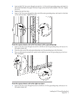
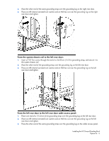
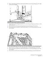
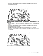
5. Repeat steps 1 through 4 for the other bottom side panel. From the middle system chassis rail to the middle side panel: 1. Connect a 36.83-cm (14.5-in) and a 15.24-cm (6-in) grounding strap with connectors together. 2. Insert a T-25 Torx screw through the end of the 36.83-cm (14.5-in) grounding strap, and secure it to the middle system chassis rail. 3. Place the end of the 15.24 (6-in) grounding strap over the grounding lug on the middle side panel. 4. Place an M8 internal serrated lock washer and an M8 hex nut over the grounding lug on the middle side panel and tighten. 5. Repeat steps 1 through 4 for the other middle side panel. From the middle system chassis rail to the top side panel: 1. Connect a 36.83-cm (14.5-in) and a 15.24-cm (6-in) grounding strap with connectors together. 2. Insert a T-25 Torx screw through the end of a 36.83-cm (14.5-in) grounding strap, and secure it to the middle system chassis rail. 3. Place the end of the 15.24-cm (6-in) grounding strap over the grounding lug on the top side panel. Installing the HP Ground Bonding Rack Option Kit 10
-
 1
1 -
2
-
3
-
4
-
 5
5 -
 6
6 -
 7
7 -
 8
8 -
 9
9 -
 10
10 -
 11
11 -
 12
12 -
 13
13 -
 14
14 -
 15
15 -
16
-
17
-
18
-
19
 |
 |
