HP 10647 10842 Rack Reference Guide - Page 37
Component Installation Overview, Refer to Appendix A, Electrostatic Discharge
 |
View all HP 10647 manuals
Add to My Manuals
Save this manual to your list of manuals |
Page 37 highlights
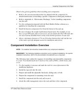
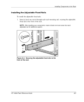
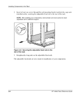
Installing Components in the Rack Observe the general guidelines when installing your components: • Refer to the user documentation that was shipped with the component for detailed instructions on installing a specific component or third-party hardware. • Refer to Appendix A, "Electrostatic Discharge," before installing components into the rack. • Use the configuration prepared with the Rack Builder Online software as a guideline for installing the components. • Install the heavier components first from the bottom of the rack up. • Be sure to balance the weight load between bayed racks. For example, if you have several UPS units and several servers, do not install all of the UPS units into one rack. Instead distribute them evenly in the bottom positions of each rack. • Allow a minimum clearance of 76 cm (30 inches) between the wall and the rear of the rack to provide adequate access for installation and service. Component Installation Overview NOTE: The stabilizer feet should be installed before any component installation. IMPORTANT: The following installation instructions are for standard installations. For specific installation instructions, refer to the documentation included with your component. The following steps outline the sequence for installing rack-mountable components in a rack. You should install zero U devices first, such as PDUs, switch boxes, and so on. 1. Use the template to measure and mark the rack for correct placement of the installation hardware. 2. Install the cage nuts into the rack. 3. Prepare and install the adjustable fixed rails, sliding rails, or both. 4. Prepare the component for mounting it into the rack. 5. Install the component into the rack and secure it. 6. Attach the cable management arm to the rack and then to the component. HP 10842 Rack Reference Guide 4-3
-
 1
1 -
2
-
3
-
4
-
5
-
6
-
7
-
8
-
9
-
10
-
11
-
12
-
13
-
14
-
15
-
16
-
17
-
18
-
19
-
20
-
21
-
22
-
23
-
24
-
25
-
26
-
27
-
28
-
29
-
30
-
31
-
 32
32 -
 33
33 -
 34
34 -
 35
35 -
 36
36 -
 37
37 -
 38
38 -
 39
39 -
 40
40 -
 41
41 -
 42
42 -
43
-
44
-
45
-
46
-
47
-
48
-
49
-
50
-
51
-
52
-
53
-
54
-
55
-
56
-
57
-
58
-
59
-
60
-
61
-
62
-
63
-
64
-
65
-
66
-
67
-
68
-
69
-
70
 |
 |