HP 10842 10842 Rack Reference Guide - Page 45
Secure the sliding rail assembly to the rack-mounting bracket
 |
View all HP 10842 manuals
Add to My Manuals
Save this manual to your list of manuals |
Page 45 highlights
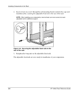
Installing Components in the Rack 4. Note the orientation of the sliding rail assembly: a. The front of the sliding rail assembly (1) allows the inner slide to move forward on ball bearings. b. The back of the sliding rail assembly (2) has a stop for the inner slide. NOTE: While matching fronts, lay one rack-mounting bracket and one sliding rail assembly together so that the screw holes are aligned. 2 1 Figure 4-8: Orienting the sliding rail assembly 5. Extend the inner slide in the sliding rail assembly until the screw holes in the rack-mounting bracket and the sliding rail assembly are aligned (1). (Refer to Figure 4-9.) Secure the sliding rail assembly to the rack-mounting bracket by inserting one 8-32 x 3/8 screw into each of the three exposed holes, two near the rear and one near the front of the sliding rail assembly. 6. Adjust the inner slide until you can access another screw hole (2) and insert one 8-32 x 3/8 screw. (Refer to Figure 4-9.) HP 10842 Rack Reference Guide 4-11
-
 1
1 -
2
-
3
-
4
-
5
-
6
-
7
-
8
-
9
-
10
-
11
-
12
-
13
-
14
-
15
-
16
-
17
-
18
-
19
-
20
-
21
-
22
-
23
-
24
-
25
-
26
-
27
-
28
-
29
-
30
-
31
-
32
-
33
-
34
-
35
-
36
-
37
-
38
-
39
-
 40
40 -
 41
41 -
 42
42 -
 43
43 -
 44
44 -
 45
45 -
 46
46 -
 47
47 -
 48
48 -
 49
49 -
 50
50 -
51
-
52
-
53
-
54
-
55
-
56
-
57
-
58
-
59
-
60
-
61
-
62
-
63
-
64
-
65
-
66
-
67
-
68
-
69
-
70
 |
 |
