HP 14-ap000 Maintenance and Service Guide - Page 52
Reverse this procedure to install the display assembly., and 3 screws from each hinge
 |
View all HP 14-ap000 manuals
Add to My Manuals
Save this manual to your list of manuals |
Page 52 highlights
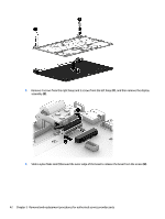
6. Remove 4 screws from the display panel (1), and then remove it (2). 7. Remove 1 screw from the top of each hinge bracket (1) and 3 screws from each hinge (2) and then remove the hinge brackets (3). Reverse this procedure to install the display assembly. 44 Chapter 5 Removal and replacement procedures for authorized service provider parts
-
 1
1 -
2
-
3
-
4
-
5
-
6
-
7
-
8
-
9
-
10
-
11
-
12
-
13
-
14
-
15
-
16
-
17
-
18
-
19
-
20
-
21
-
22
-
23
-
24
-
25
-
26
-
27
-
28
-
29
-
30
-
31
-
32
-
33
-
34
-
35
-
36
-
37
-
38
-
39
-
40
-
41
-
42
-
43
-
44
-
45
-
46
-
 47
47 -
 48
48 -
 49
49 -
 50
50 -
 51
51 -
 52
52 -
 53
53 -
 54
54 -
 55
55 -
 56
56 -
 57
57 -
58
-
59
-
60
-
61
-
62
-
63
-
64
-
65
-
66
-
67
-
68
 |
 |

6.
Remove 4 screws from the display panel
(1)
, and then remove it
(2)
.
7.
Remove 1 screw from the top of each hinge bracket
(1)
and 3 screws from each hinge
(2)
and then
remove the hinge brackets
(3)
.
Reverse this procedure to install the display assembly.
44
Chapter 5
Removal and replacement procedures for authorized service provider parts