HP 14-r200 Maintenance and Service Guide - Page 86
the display., that secure the bezel
 |
View all HP 14-r200 manuals
Add to My Manuals
Save this manual to your list of manuals |
Page 86 highlights
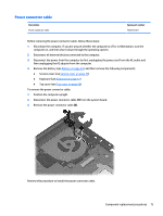
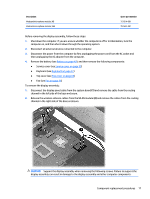
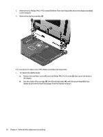
3. Remove the six Phillips PM2.5×4.0 screws (1) (three from each hinge) that secure the display assembly to the computer. 4. Remove the display assembly (2). If it is necessary to replace any of the display assembly subcomponents: 1. To remove the display bezel: a. Remove the two Mylar covers (1) and two Phillips PM2.0×3.0 screws (2) that secure the bezel to the display. b. Flex the inside of the top edge (3), the left and right sides (4), and the bottom edge (5) of the display bezel until the bezel disengages from the display enclosure. 78 Chapter 4 Removal and replacement procedures
-
 1
1 -
2
-
3
-
4
-
5
-
6
-
7
-
8
-
9
-
10
-
11
-
12
-
13
-
14
-
15
-
16
-
17
-
18
-
19
-
20
-
21
-
22
-
23
-
24
-
25
-
26
-
27
-
28
-
29
-
30
-
31
-
32
-
33
-
34
-
35
-
36
-
37
-
38
-
39
-
40
-
41
-
42
-
43
-
44
-
45
-
46
-
47
-
48
-
49
-
50
-
51
-
52
-
53
-
54
-
55
-
56
-
57
-
58
-
59
-
60
-
61
-
62
-
63
-
64
-
65
-
66
-
67
-
68
-
69
-
70
-
71
-
72
-
73
-
74
-
75
-
76
-
77
-
78
-
79
-
80
-
 81
81 -
 82
82 -
 83
83 -
 84
84 -
 85
85 -
 86
86 -
 87
87 -
 88
88 -
 89
89 -
 90
90 -
 91
91 -
92
-
93
-
94
-
95
-
96
-
97
-
98
-
99
-
100
-
101
-
102
-
103
-
104
-
105
-
106
-
107
-
108
-
109
-
110
-
111
-
112
-
113
-
114
-
115
-
116
-
117
-
118
-
119
-
120
-
121
-
122
-
123
-
124
-
125
-
126
-
127
-
128
-
129
-
130
-
131
-
132
-
133
-
134
-
135
-
136
-
137
-
138
-
139
-
140
-
141
-
142
-
143
-
144
-
145
-
146
-
147
-
148
 |
 |
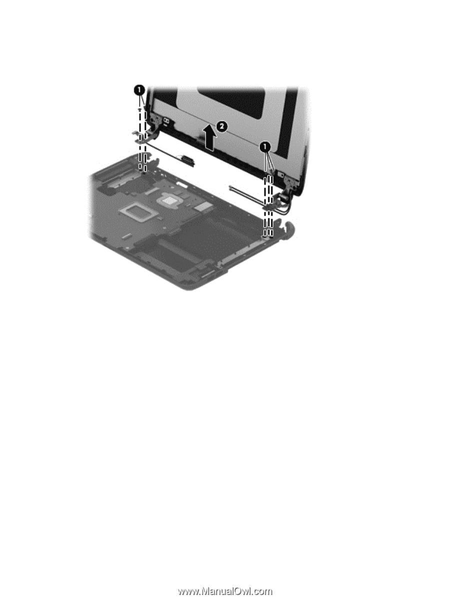
3.
Remove the six Phillips PM2.5×4.0 screws
(1)
(three from each hinge) that secure the display assembly
to the computer.
4.
Remove the display assembly
(2)
.
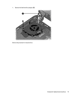
If it is necessary to replace any of the display assembly subcomponents:
1.
To remove the display bezel:
a.
Remove the two Mylar covers
(1)
and two Phillips PM2.0×3.0 screws
(2)
that secure the bezel to
the display.
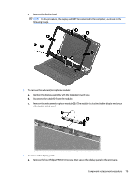
b.
Flex the inside of the top edge
(3)
, the left and right sides
(4)
, and the bottom edge
(5)
of the
display bezel until the bezel disengages from the display enclosure.
78
Chapter 4
Removal and replacement procedures