HP 15-bf000 15-ba199 Models: 15-ba000 - 15-ba099 Models: 15-bf100 - 15-bf199 M - Page 72
Speaker cable, TouchPad button board cable
 |
View all HP 15-bf000 manuals
Add to My Manuals
Save this manual to your list of manuals |
Page 72 highlights
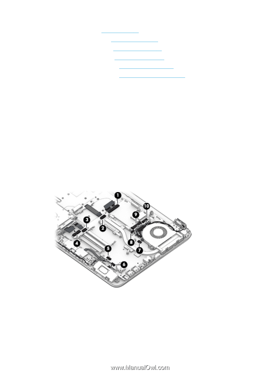
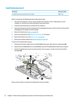
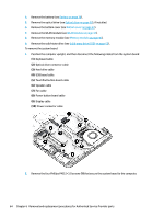
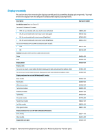
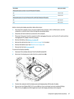
4. Remove the battery (see Battery on page 38). 5. Remove the optical drive (see Optical drive on page 39), if installed. 6. Remove the bottom cover (see Bottom cover on page 42). 7. Remove the WLAN module (see WLAN module on page 44). 8. Remove the memory module (see Memory module on page 46). 9. Remove the solid-state drive (see Solid-state drive (SSD) on page 55). To remove the system board: 1. Position the computer upright, and then disconnect the following cables from the system board: (1): Keyboard cable (2): Optical drive connector cable (3): Hard drive cable (4): USB board cable (5): TouchPad button board cable (6): Speaker cable (7): Fan cable (8): Power button board cable (9): Display cable (10): Power connector cable 2. Remove the four Phillips PM2.5×3.0 screws (1) that secure the system board to the computer. 64 Chapter 6 Removal and replacement procedures for Authorized Service Provider parts
-
 1
1 -
2
-
3
-
4
-
5
-
6
-
7
-
8
-
9
-
10
-
11
-
12
-
13
-
14
-
15
-
16
-
17
-
18
-
19
-
20
-
21
-
22
-
23
-
24
-
25
-
26
-
27
-
28
-
29
-
30
-
31
-
32
-
33
-
34
-
35
-
36
-
37
-
38
-
39
-
40
-
41
-
42
-
43
-
44
-
45
-
46
-
47
-
48
-
49
-
50
-
51
-
52
-
53
-
54
-
55
-
56
-
57
-
58
-
59
-
60
-
61
-
62
-
63
-
64
-
65
-
66
-
 67
67 -
 68
68 -
 69
69 -
 70
70 -
 71
71 -
 72
72 -
 73
73 -
 74
74 -
 75
75 -
 76
76 -
 77
77 -
78
-
79
-
80
-
81
-
82
-
83
-
84
-
85
-
86
-
87
-
88
-
89
-
90
-
91
-
92
-
93
-
94
-
95
-
96
-
97
-
98
-
99
-
100
-
101
-
102
-
103
-
104
-
105
-
106
-
107
-
108
-
109
-
110
-
111
-
112
-
113
-
114
-
115
-
116
-
117
-
118
-
119
-
120
-
121
-
122
-
123
-
124
-
125
-
126
 |
 |