HP 15-bs000 Maintenance and Service Guide - Page 76
unplugging the power cord from the AC outlet and then, unplugging the AC adapter from the computer.
 |
View all HP 15-bs000 manuals
Add to My Manuals
Save this manual to your list of manuals |
Page 76 highlights
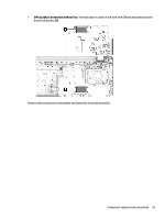
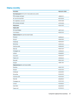
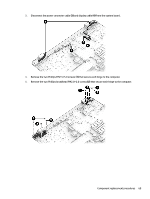
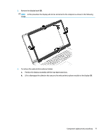
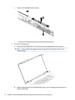
Description Rose gold Silk gold Hinges (left and right) Hinge covers Left, jet black Right, jet black Left, snow white Right, snow white Left, pike silver Right, pike silver Left, rose gold Right, rose gold Left, champagne rose Right, champagne rose Left, silk gold Right, silk gold Webcam/microphone module HD VGA Touch control board (includes tape and EMI foil) Spare part number 933301-001 L00662-001 926527-001 926533-001 926534-001 926535-001 926536-001 926537-001 926538-001 926542-001 926543-001 926544-001 926545-001 928883-001 928884-001 919471-003 919472-003 926532-001 Before removing the display assembly, follow these steps: 1. Shut down the computer. If you are unsure whether the computer is off or in Hibernation, turn the computer on, and then shut it down through the operating system. 2. Disconnect all external devices connected to the computer. 3. Disconnect the power from the computer by first unplugging the power cord from the AC outlet and then unplugging the AC adapter from the computer. 4. Remove the battery (see Battery on page 32). 5. Remove the optical drive (see Optical drive on page 34). 6. Remove the bottom cover (see Bottom cover on page 41). 7. Remove the fan (see Fan on page 58). 8. Remove the heat sink (see Heat sink assembly on page 59). To remove the display assembly: 1. Remove the black Mylar tape from near each hinge (1). 2. Disconnect the wireless antenna cables from the WLAN module (2). 68 Chapter 6 Removal and replacement procedures for Authorized Service Provider parts
-
 1
1 -
2
-
3
-
4
-
5
-
6
-
7
-
8
-
9
-
10
-
11
-
12
-
13
-
14
-
15
-
16
-
17
-
18
-
19
-
20
-
21
-
22
-
23
-
24
-
25
-
26
-
27
-
28
-
29
-
30
-
31
-
32
-
33
-
34
-
35
-
36
-
37
-
38
-
39
-
40
-
41
-
42
-
43
-
44
-
45
-
46
-
47
-
48
-
49
-
50
-
51
-
52
-
53
-
54
-
55
-
56
-
57
-
58
-
59
-
60
-
61
-
62
-
63
-
64
-
65
-
66
-
67
-
68
-
69
-
70
-
 71
71 -
 72
72 -
 73
73 -
 74
74 -
 75
75 -
 76
76 -
 77
77 -
 78
78 -
 79
79 -
 80
80 -
 81
81 -
82
-
83
-
84
-
85
-
86
-
87
-
88
-
89
-
90
-
91
-
92
-
93
-
94
-
95
-
96
-
97
-
98
-
99
-
100
-
101
-
102
-
103
-
104
-
105
-
106
-
107
-
108
-
109
-
110
-
111
-
112
-
113
-
114
 |
 |