HP 15-f001xx HP 15 Notebook PC Maintenance and Service Guide - Page 57
from the bracket and separate the front edges of the, hard drive rubber bracket from the hard drive
 |
View all HP 15-f001xx manuals
Add to My Manuals
Save this manual to your list of manuals |
Page 57 highlights
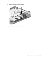
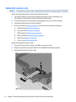
3. Release the hard drive connector cable from the clips. NOTE: You will disconnect the hard drive connector cable from the system board when you remove the system board. 4. If it is necessary to disassemble the hard drive, perform the following steps: a. Remove the four Phillips M3.0×3.5 screws (1) from the bracket and separate the front edges of the hard drive rubber bracket from the hard drive b. Disassemblying the hard drive Component replacement procedures 47
-
 1
1 -
2
-
3
-
4
-
5
-
6
-
7
-
8
-
9
-
10
-
11
-
12
-
13
-
14
-
15
-
16
-
17
-
18
-
19
-
20
-
21
-
22
-
23
-
24
-
25
-
26
-
27
-
28
-
29
-
30
-
31
-
32
-
33
-
34
-
35
-
36
-
37
-
38
-
39
-
40
-
41
-
42
-
43
-
44
-
45
-
46
-
47
-
48
-
49
-
50
-
51
-
 52
52 -
 53
53 -
 54
54 -
 55
55 -
 56
56 -
 57
57 -
 58
58 -
 59
59 -
 60
60 -
 61
61 -
 62
62 -
63
-
64
-
65
-
66
-
67
-
68
-
69
-
70
-
71
-
72
-
73
-
74
-
75
-
76
-
77
-
78
-
79
-
80
-
81
-
82
-
83
-
84
-
85
-
86
-
87
-
88
-
89
-
90
-
91
-
92
-
93
-
94
-
95
-
96
-
97
 |
 |
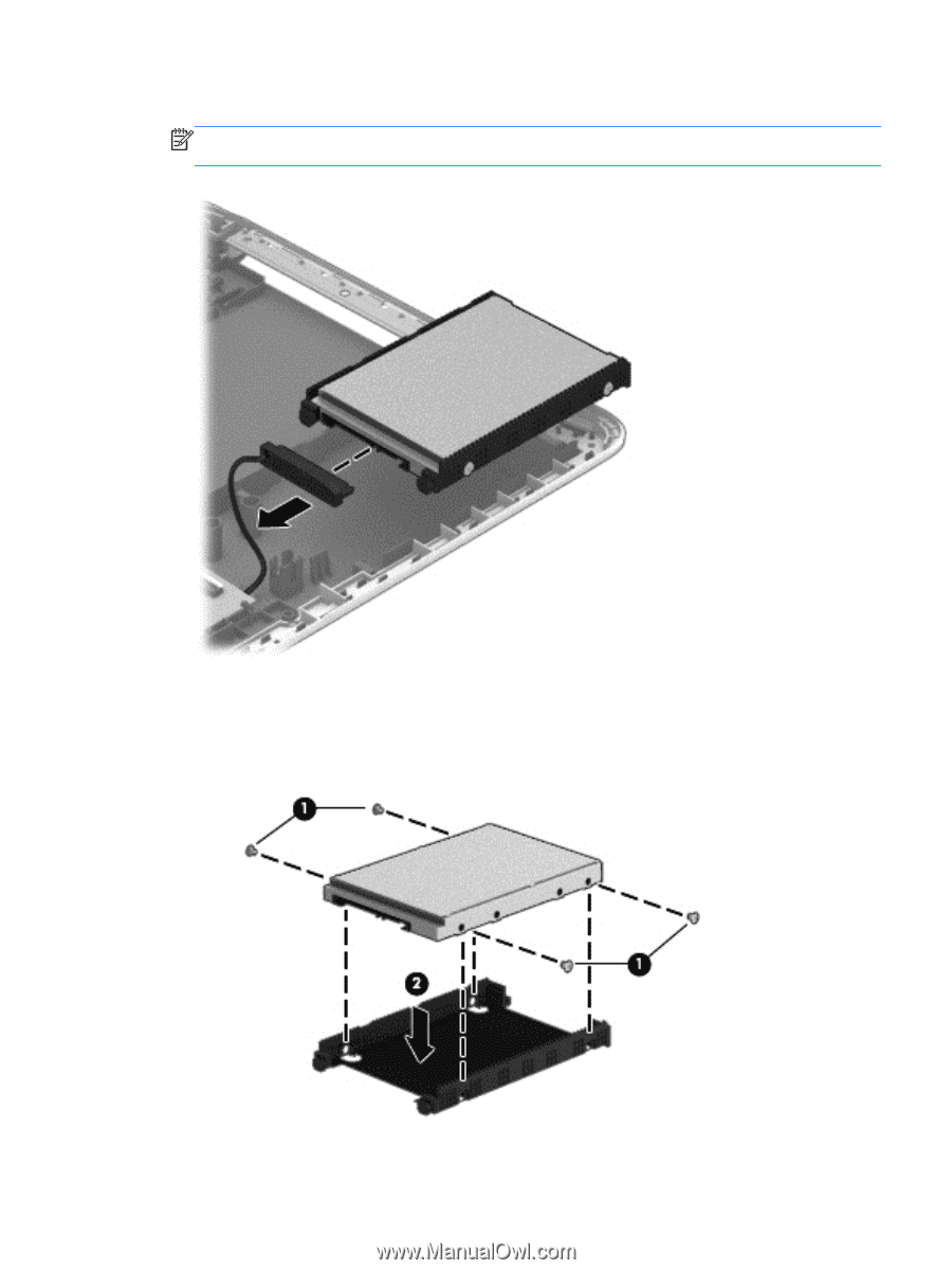
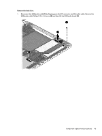
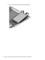
3.
Release the hard drive connector cable from the clips.
NOTE:
You will disconnect the hard drive connector cable from the system board when you remove
the system board.
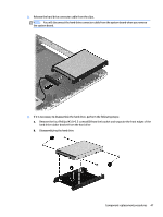
4.
If it is necessary to disassemble the hard drive, perform the following steps:
a.
Remove the four Phillips M3.0×3.5 screws
(1)
from the bracket and separate the front edges of the
hard drive rubber bracket from the hard drive
b.
Disassemblying the hard drive
Component replacement procedures
47