HP 15-f001xx HP 15 Notebook PC Maintenance and Service Guide - Page 73
Heat sink assembly
 |
View all HP 15-f001xx manuals
Add to My Manuals
Save this manual to your list of manuals |
Page 73 highlights
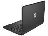
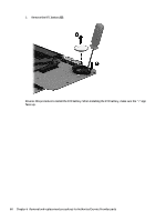
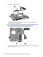
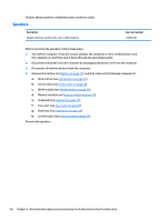
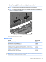
Heat sink assembly Description Heat sink Spare part number 749040-001 NOTE: To properly ventilate the computer, allow at least 7.6 cm (3 in) of clearance on the left side of the computer. The computer uses an electric fan for ventilation. The fan is controlled by a temperature sensor and is designed to turn on automatically when high temperature conditions exist. These conditions are affected by high external temperatures, system power consumption, power management/battery conservation configurations, battery fast charging, and software requirements. Exhaust air is displaced through the ventilation grill located on the left side of the computer. Before removing the fan/heat sink assembly, follow these steps: 1. Turn off the computer. If you are unsure whether the computer is off or in Hibernation, turn the computer on, and then shut it down through the operating system. 2. Disconnect the power from the computer by unplugging the power cord from the computer. 3. Disconnect all external devices from the computer. 4. Remove the battery (see Battery on page 27), and then remove the following components: a. Optical drive (see Optical drive on page 32). b. Service door (see Service door on page 28). c. WLAN module (see WLAN module on page 30). d. Memory module (see Memory module on page 29). e. Keyboard (see Keyboard on page 37). f. Top cover (see Top cover on page 40). g. Hard drive (see Hard drive on page 44). h. System board (see System board on page 55). Remove the heat sink assembly: 1. Turn the system board upside down, with the front toward you. 2. Disconnect the fan cable from the system board. 3. Following the 1, 2, 3, 4 sequence stamped into the fan/heat sink assembly, loosen the four Phillips M2.0×10.0 captive screws (1) that secure the fan/heat sink assembly to the system board. Component replacement procedures 63
-
 1
1 -
2
-
3
-
4
-
5
-
6
-
7
-
8
-
9
-
10
-
11
-
12
-
13
-
14
-
15
-
16
-
17
-
18
-
19
-
20
-
21
-
22
-
23
-
24
-
25
-
26
-
27
-
28
-
29
-
30
-
31
-
32
-
33
-
34
-
35
-
36
-
37
-
38
-
39
-
40
-
41
-
42
-
43
-
44
-
45
-
46
-
47
-
48
-
49
-
50
-
51
-
52
-
53
-
54
-
55
-
56
-
57
-
58
-
59
-
60
-
61
-
62
-
63
-
64
-
65
-
66
-
67
-
 68
68 -
 69
69 -
 70
70 -
 71
71 -
 72
72 -
 73
73 -
 74
74 -
 75
75 -
 76
76 -
 77
77 -
 78
78 -
79
-
80
-
81
-
82
-
83
-
84
-
85
-
86
-
87
-
88
-
89
-
90
-
91
-
92
-
93
-
94
-
95
-
96
-
97
 |
 |