HP 15-f001xx HP 15 Notebook PC Maintenance and Service Guide - Page 77
Display assembly, Reverse this procedure to install the speaker.
 |
View all HP 15-f001xx manuals
Add to My Manuals
Save this manual to your list of manuals |
Page 77 highlights
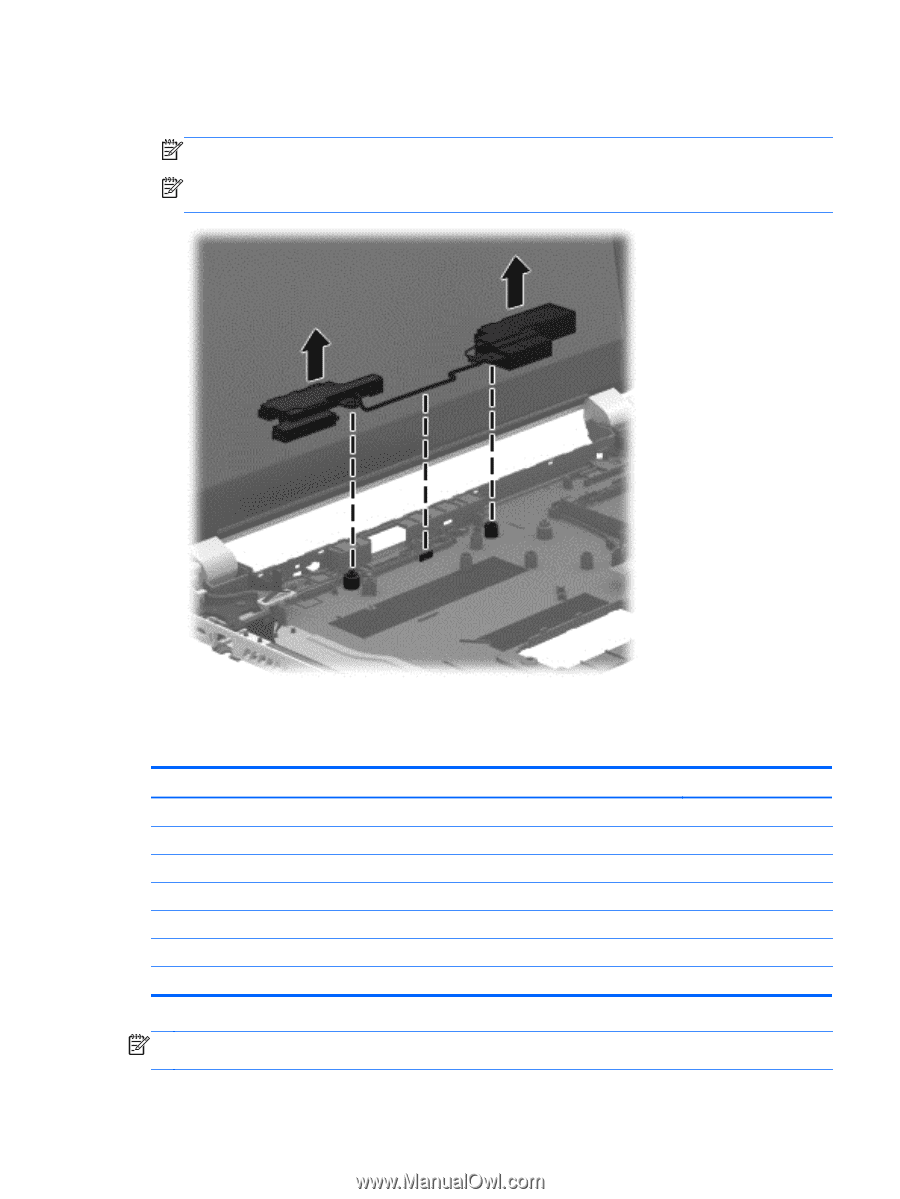
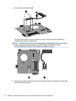
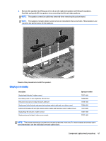
▲ Remove the speakers by lifting up on the clip on the right side speaker and lifting the speakers. Carefully and gently lift the speaker wire connecting the left and right speakers. NOTE: The speaker connection cable was removed when removing the system board. NOTE: The speakers include rubber isolators that are installed in the screw holes. These isolators are crucial to the performance of the speakers. Reverse this procedure to install the speaker. Display assembly Description Display bezel (includes 2 rubber screws) Raw display panel, 15.6-in, BrightView, HD, LED, SVA Webcamera/microphone module (includes adhesive) Display panel cable (includes webcamera/microphone module cable and two rubber screws) Antenna Kit (includes left and right wireless antenna cables and transceivers and 2 rubber screws) Display Hinge Kit (includes 2 rubber screws): Display enclosure (includes 2 rubber screw covers): Spare part number 776774-001 732080-001 776787-001 732066-001 776770-001 732072-001 776771-001 NOTE: The display assembly is spared at the subcomponent level only. For more display assembly spare part information, see the individual removal subsections. Component replacement procedures 67
-
 1
1 -
2
-
3
-
4
-
5
-
6
-
7
-
8
-
9
-
10
-
11
-
12
-
13
-
14
-
15
-
16
-
17
-
18
-
19
-
20
-
21
-
22
-
23
-
24
-
25
-
26
-
27
-
28
-
29
-
30
-
31
-
32
-
33
-
34
-
35
-
36
-
37
-
38
-
39
-
40
-
41
-
42
-
43
-
44
-
45
-
46
-
47
-
48
-
49
-
50
-
51
-
52
-
53
-
54
-
55
-
56
-
57
-
58
-
59
-
60
-
61
-
62
-
63
-
64
-
65
-
66
-
67
-
68
-
69
-
70
-
71
-
 72
72 -
 73
73 -
 74
74 -
 75
75 -
 76
76 -
 77
77 -
 78
78 -
 79
79 -
 80
80 -
 81
81 -
 82
82 -
83
-
84
-
85
-
86
-
87
-
88
-
89
-
90
-
91
-
92
-
93
-
94
-
95
-
96
-
97
 |
 |